For our midterm project, we were required to make a press-fit construction system. Our original plans, which included creating a dragon and a trebuchet, were deemed either too complex or too violent for the nature of this course, and as such were scrapped. We decided instead to create a marble automata and a mechanical flapping owl, projects which we believed sufficiently balanced safety, plausibility, and coolness. Although we both helped and consulted the other partner when we encountered difficulties, we largely split the workload of the projects. Marie largely claimed responsibility for the marble automata, and Mikaela largely claimed responsibility for the flapping owl.
Also, as a general note: we encountered some difficulties using WordPress’s internal editing software. As far as we know, the media library (and attached photos at the bottom of this page) are updated, cropped, and scaled to browser-appropriate sizes; however, we aren’t entirely sure if these updates carried over to the in-text images as well.
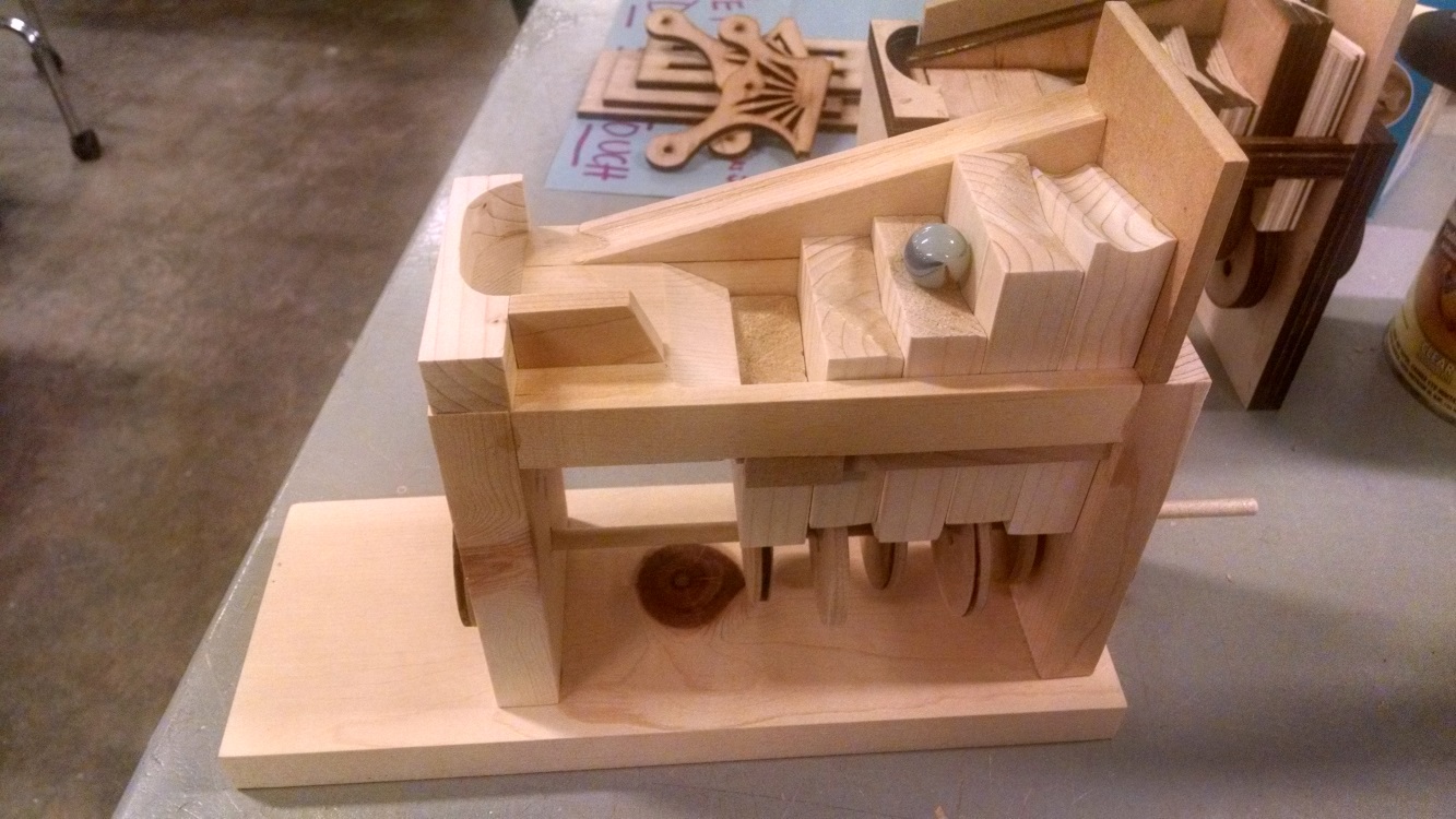
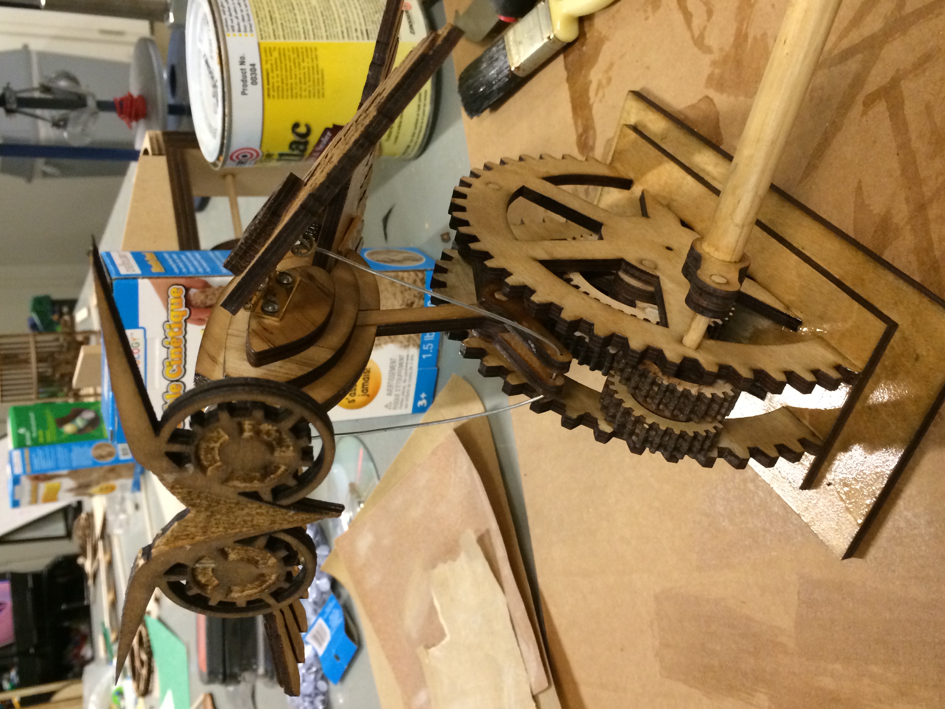
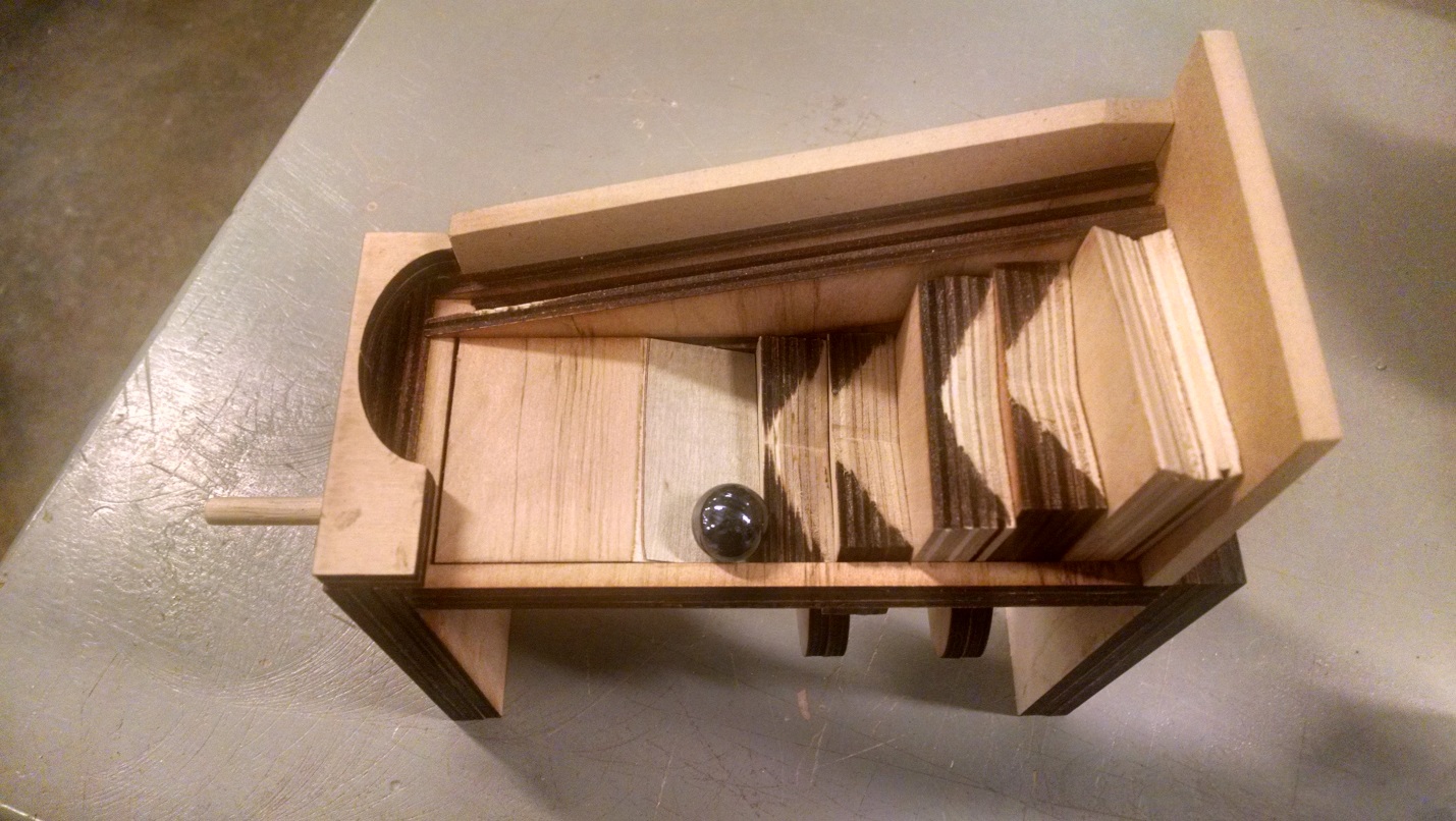
Below are final images of the completed projects, although documentation for the entire construction process is also contained below:
The Marble Climber
The Owl
The Marble Climber Automata (Marie)
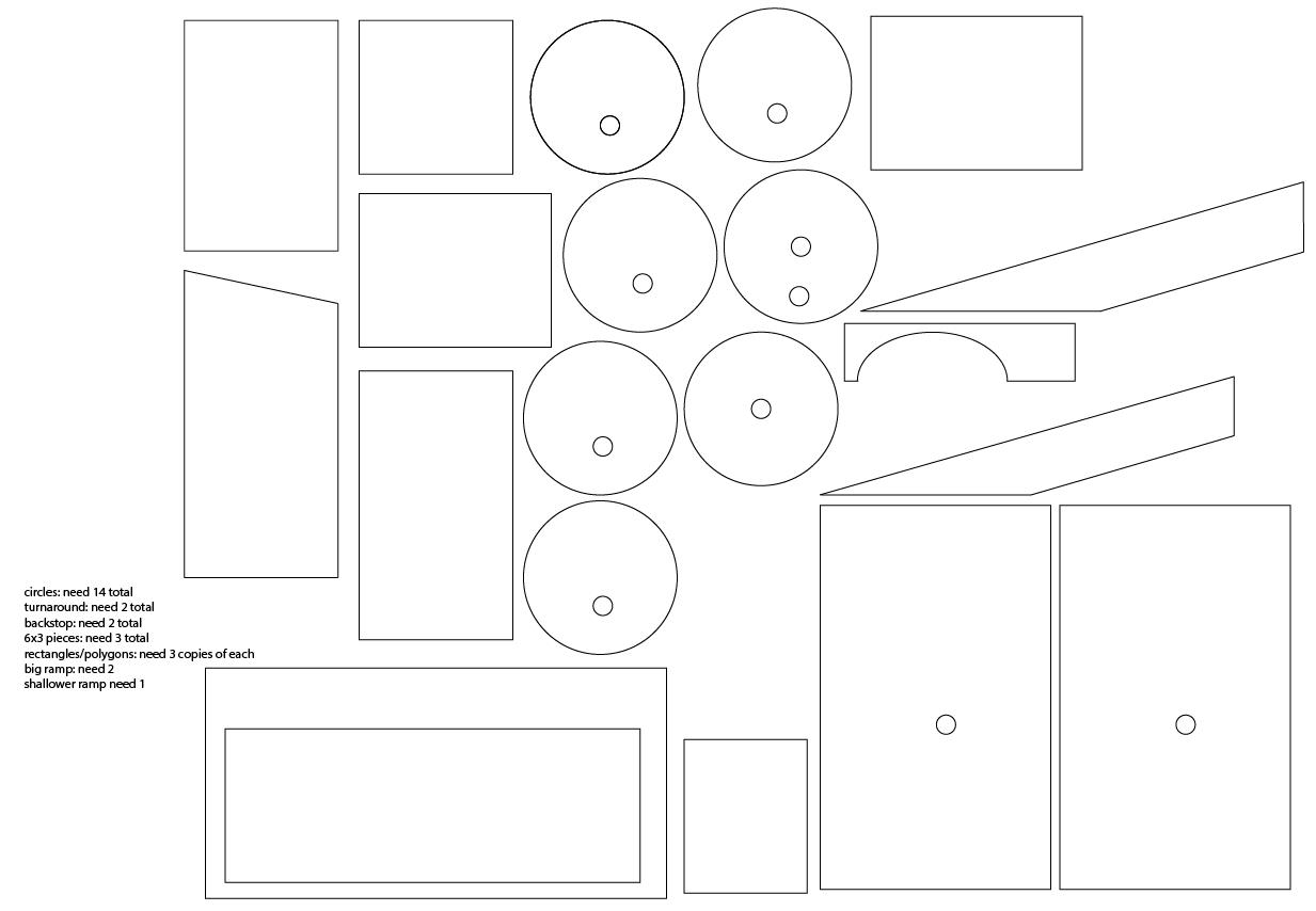
I first found the plans online from: http://www.stevedgood.com/marbleautomata.pdf. Steve Good also has many other free plans which are also awesome. Additionally, there were further instructions on assembly and process at http://www.youtube.com/user/sdgood. I felt this project would be a reasonable level of difficulty, but not too difficult to where it couldn’t be finished. In Illustrator, I recreated the plans from Steve’s site, which was fairly simple, as most all the shapes to be cut were either circles or rectangles. After converting everything to illustrator, plans were sent to engravelab and parts were laser cut. In the illustrator file itself I noted how many of each part needed to be cut. The original plans called for ¾ inch wood, so I figured that gluing together 3 ¼ inch pieces would be equivalent. I didn’t realize then that ¼ inch wood was actually thinner, which made me modify the design when it came to the ramp.
After everything was laser cut, I glued pieces together with wood glue and allowed them to dry overnight.
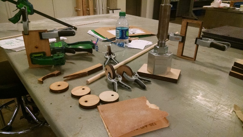
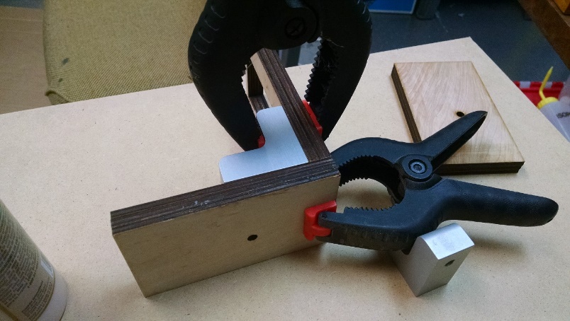
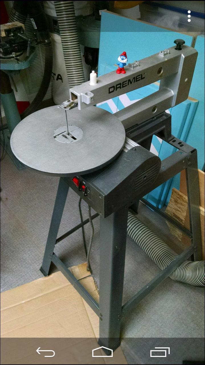
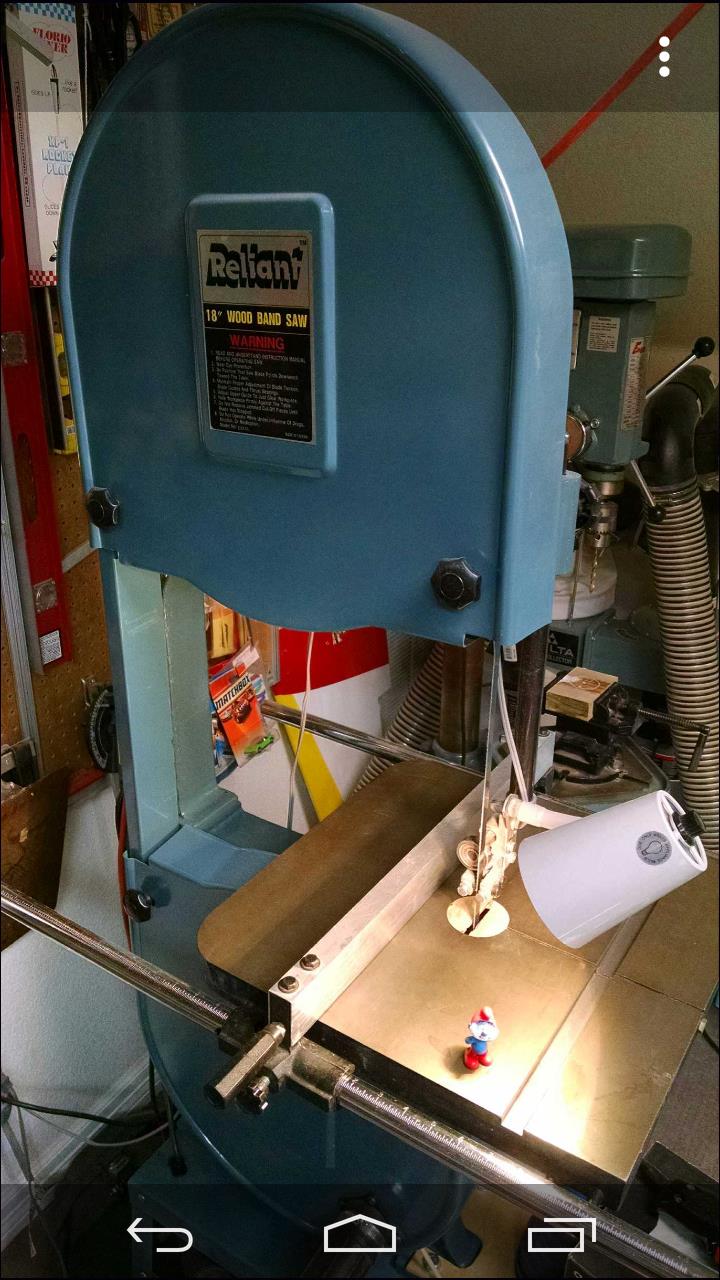
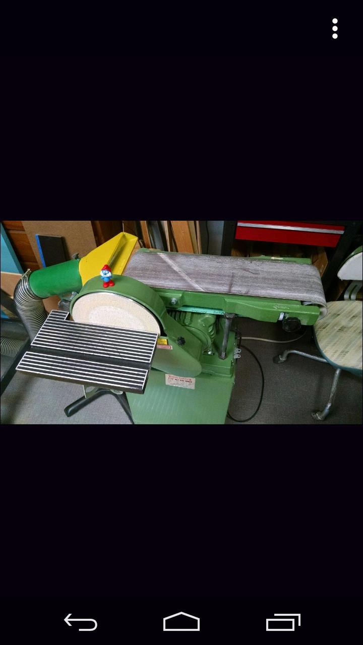
Later that week I went home for spring break, and completed the majority of the project there. My dad builds and flies R/C model airplanes, and we have a cramped attic space turned hobby shop above my house. For the V that needed to be cut in each of the steps I used the scroll saw with the table tilted at about a 15 degree angle. Below is the scroll saw, Papa Smurf for scale.
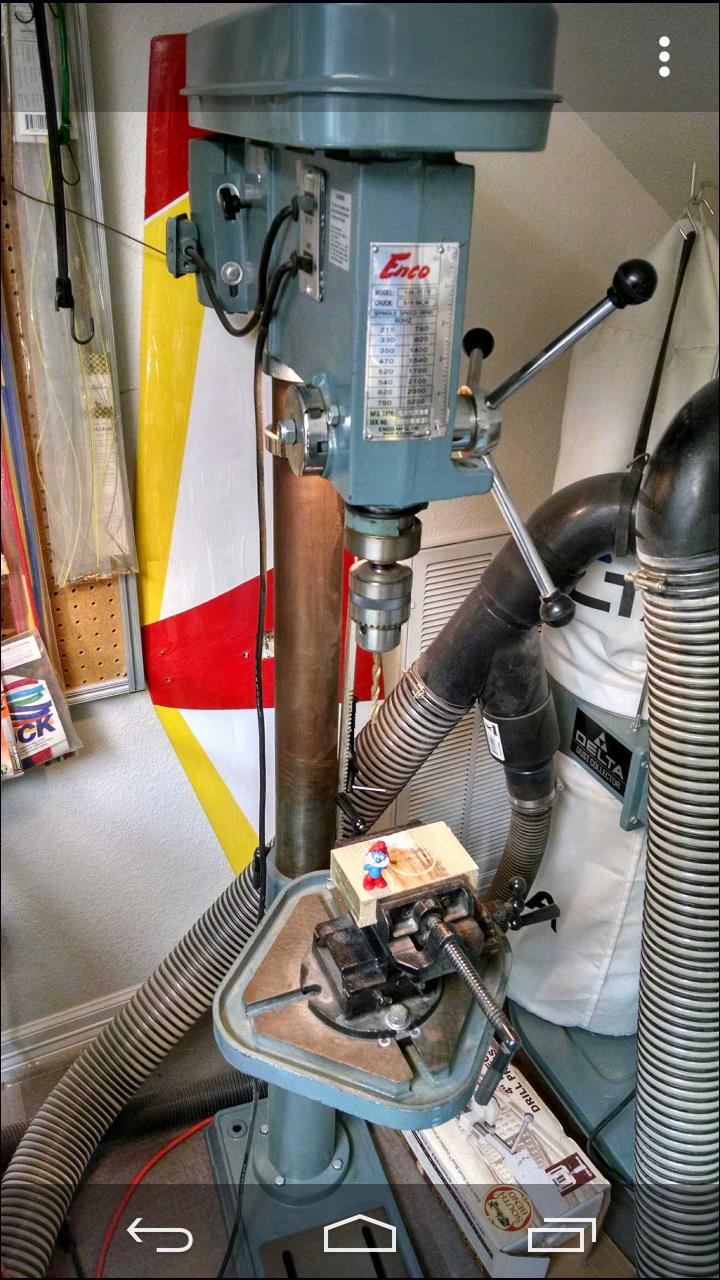
There were actually quite a few problems I didn’t foresee in laser cutting this project in addition to the thinner wood. One was that in gluing the circles together, the holes didn’t align perfectly, and so they didn’t sit at 90 degrees to the dowel that went through them. Using one circle instead of gluing two together actually worked better. To lessen the impact of the slanting discs I drilled another hole in a few with a hand drill because I didn’t know our drill press was functioning at the time. This helped bit, but the drill press would later prove to be much better. I also used a de-burring tool to smooth out the inside of the discs so the dowel would fit. The rest of the mechanism came together fairly smoothly, with the addition of a few more pieces to prevent the marble from falling off the model. After the debacle with the circles, I decided that I would make another model, and leave the laser cut one a bit rough.
The next model I built following advice from Steve’s Youtube tutorials. I used wood left over from what I think was my brother’s attempt at a crossbow. I used 1 inch wood that’s actually closest to ¾ inches. I made all major cuts with the band saw, and the Vs again with the smaller scroll saw turned at an angle.
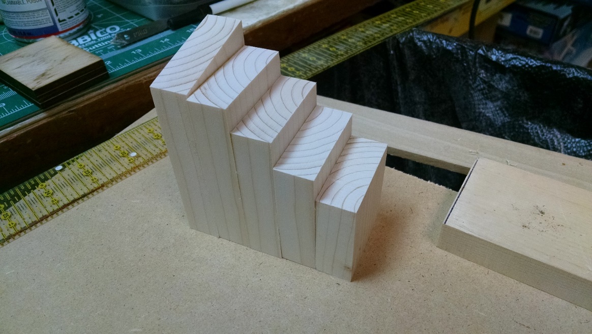
For the circles I used a circle cutter that was 21/4 inches in diameter and made a hole in the center as it cut. For this reason, all of the circles have a hole in the middle. Then I made additional holes where necessary. After everything was cut, I sanded all the pieces with the belt sander and/or sand paper.
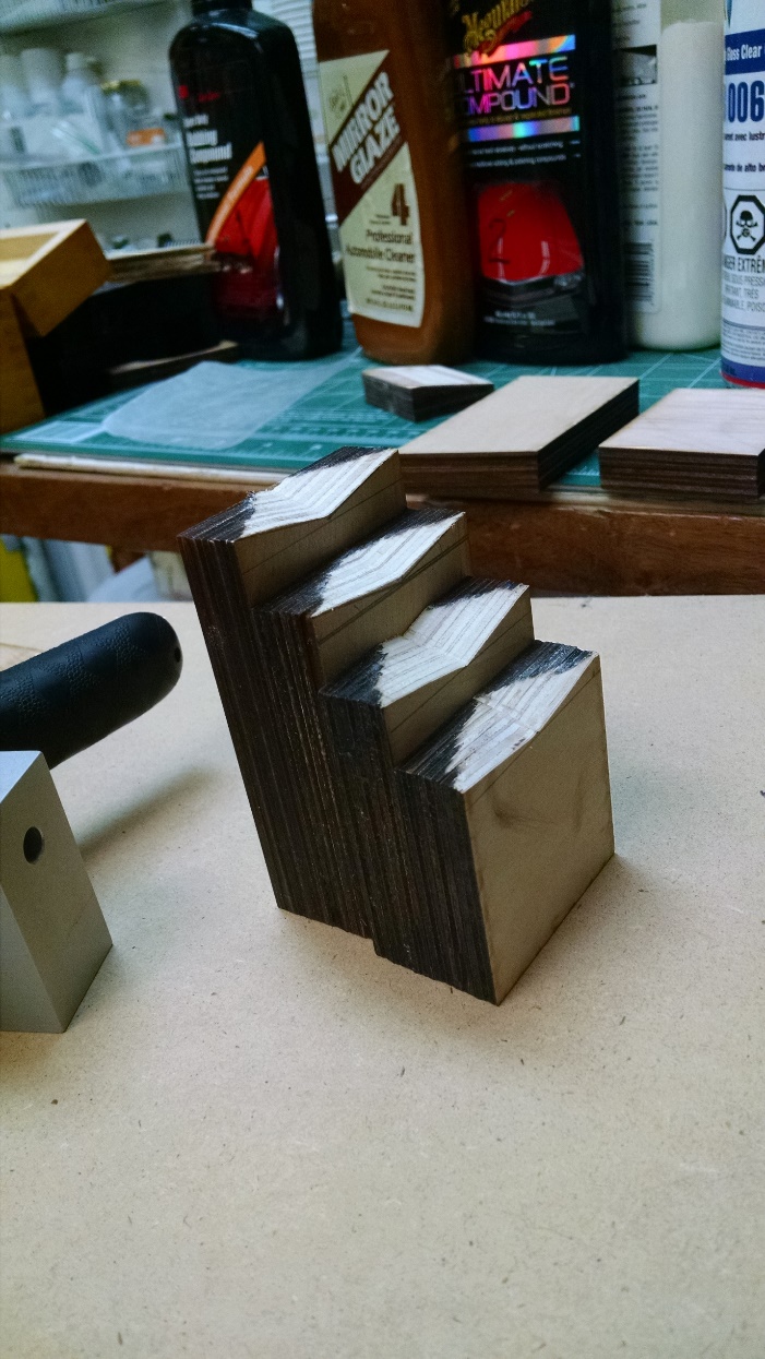
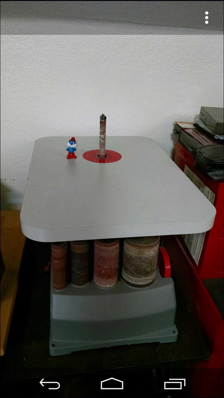
To make the grooves on the ramp and 5th piston, I used this oscillating sander (not quite sure what it’s called, but it moves up and down). And to make the turnaround, I cut out a piece using the scroll saw to make the curved edge. I also made a base for a person to hold onto with one hand, and turn the crank with the other. I took into consideration that most people (myself included, sorry Mikaela!) are right handed, and made it according to what I thought would be most pleasing to look at while operating.
For assembly, I used wood glue or CA glue (for faster drying on some of the circles). Once all the pistons slid smoothly in the chamber, I decided to paint on a clear coat for both looks and to reduce friction. Unfortunately, that had the opposite effect, and I ended up sanding most of it off. Additionally, I added a few smaller wood parts to the inside of the chamber to prevent pistons from moving sideways so that they could only move up and down. I considered painting the machine, but in the end decided I liked the timeless plain wood look and felt that any extra color/paint would take away from the pure mechanistic feel.
The Owl (Mikaela)
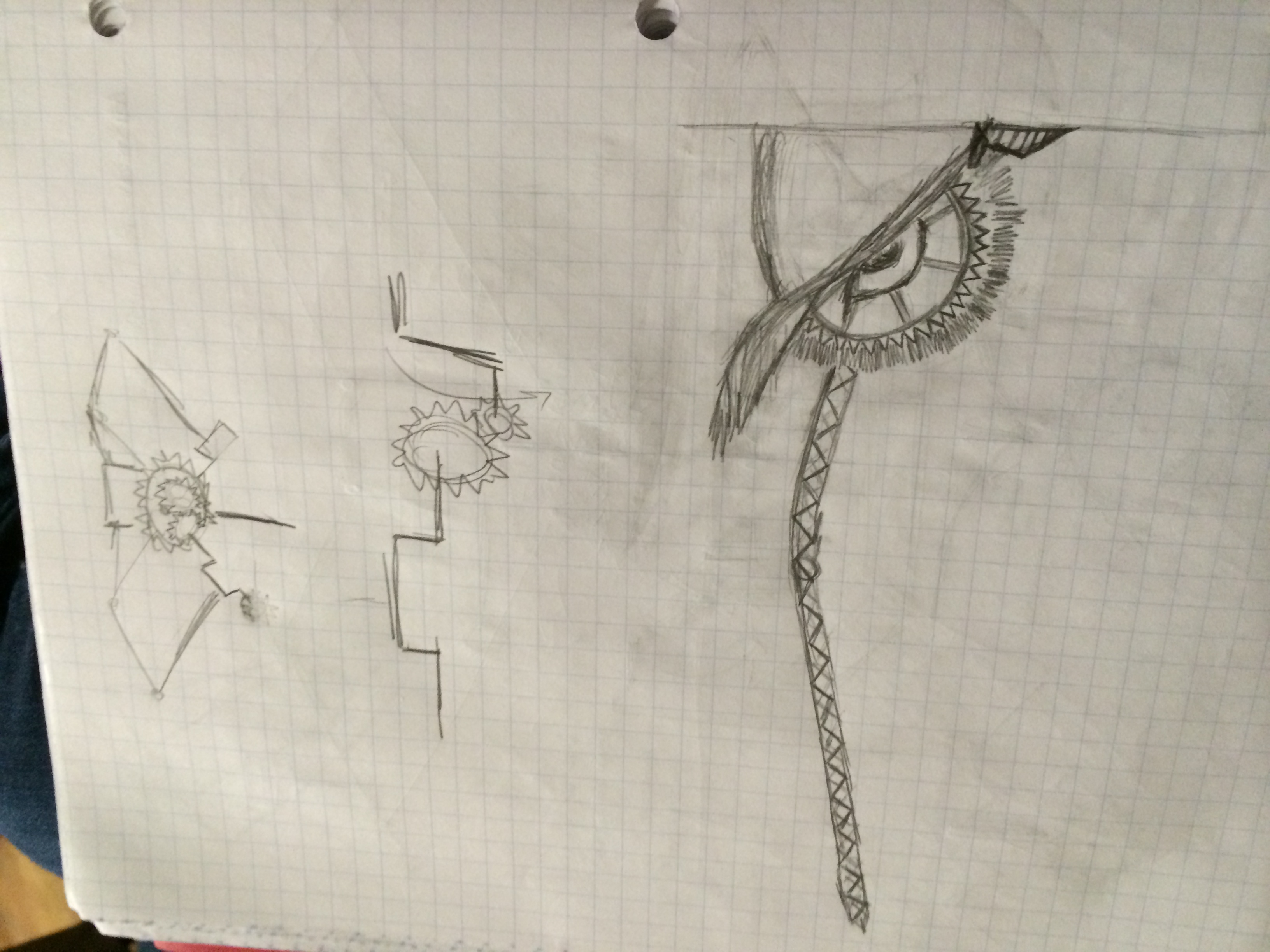
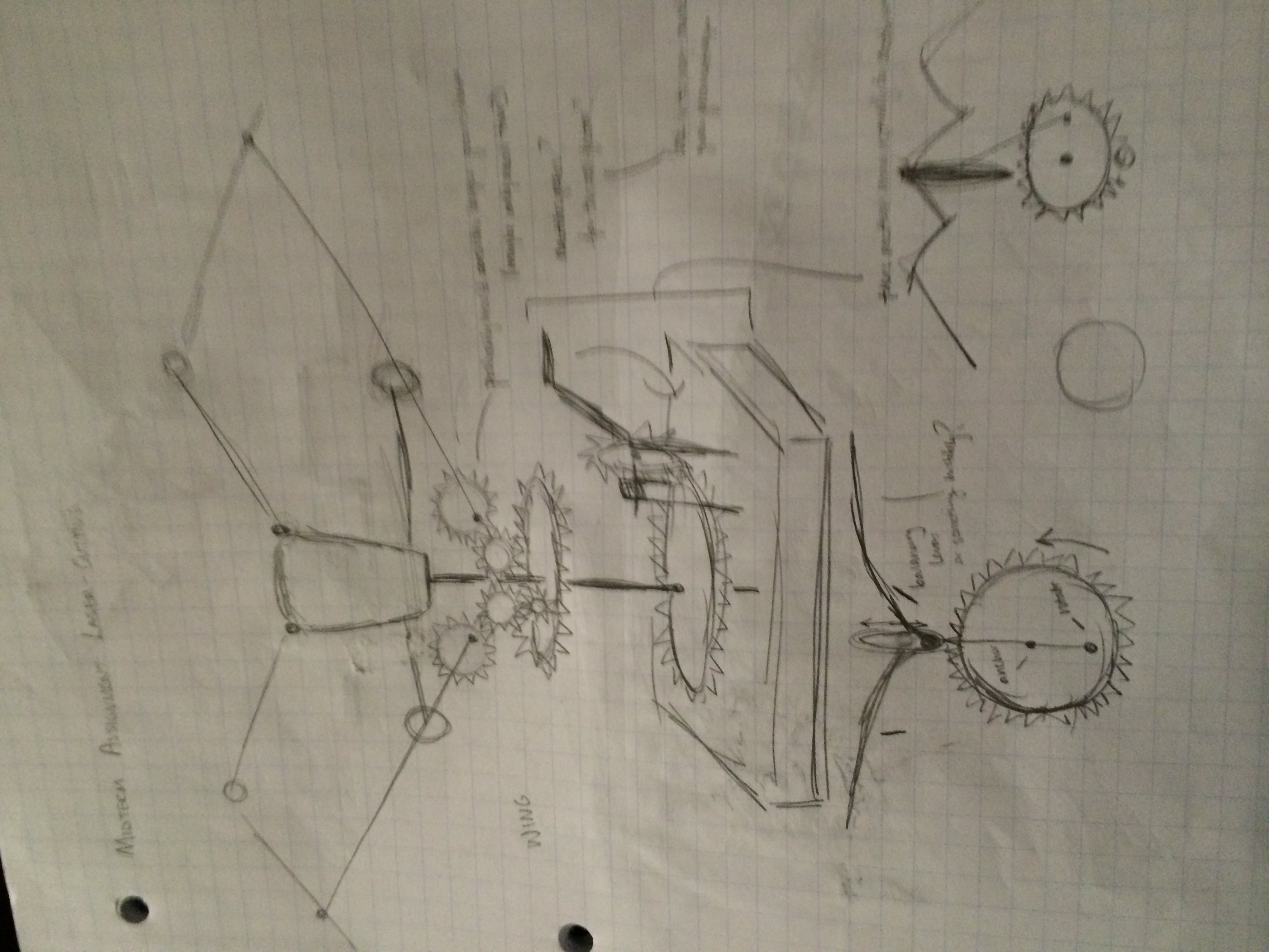
The original idea for the owl mechanism was difficult to envision. I originally experimented with several slightly different gear mechanisms to emulate the flapping movement properly, which proved difficult to create with a gear-system (at least, difficult for my level of experience). I ended up modifying designs from a DIY website known as instructables.com, which offered designs for a laser cut cupid that demonstrated the flapping movements that I wished to see in my final object. A couple of the hand-drawn sketches used for inspiration for the aesthetic touches, along with the cupid designs used as inspiration for the mechanical touches, are shown below:
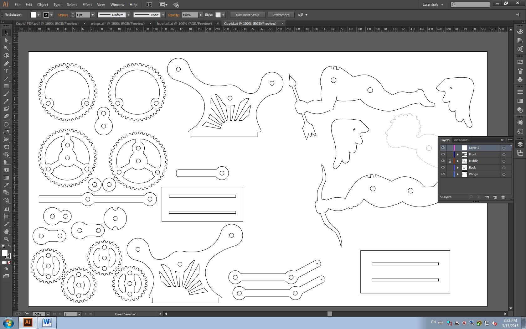
The .pdf files for the cupid are downloadable for free from the link above, although I had to re-trace the images into my version of illustrator so that I could make the path edits necessary to modify the designs into a more owl-ish shape. I kept all of the gear structure used in the original, but I modified the base and the entire body of the flying portion. The designs modified for owl are shown below:
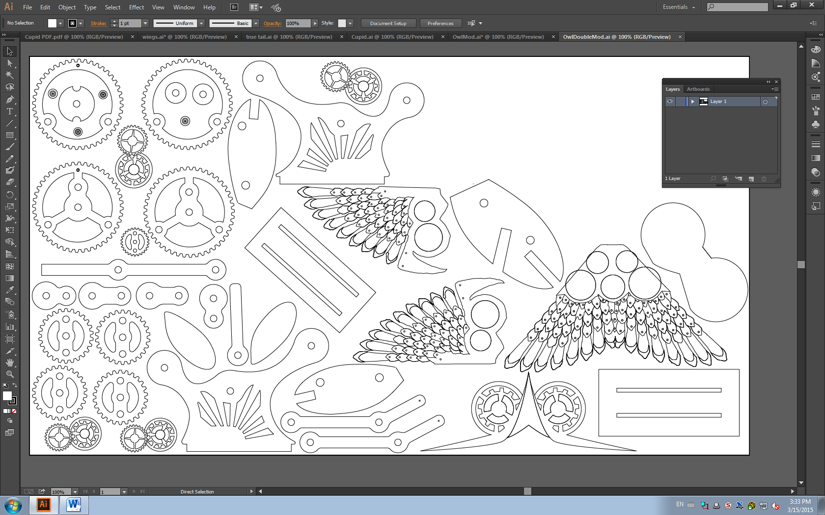
Most importantly, I thickened the body, which in turn allowed me to support a greatly increased body mass, which was caused by the addition of the wings and tail. I then decided to utilize the engraving functions of the OEDK’s laser cutter for detail work. These details were most prevalent in the wings and tail of the owl, although I also used them in the face.
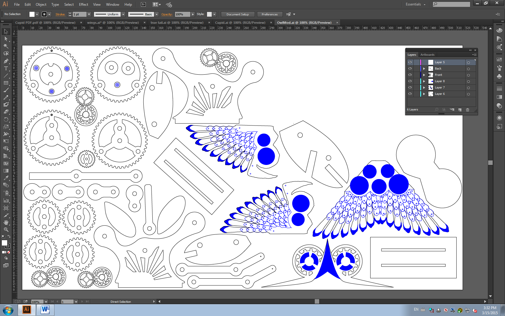
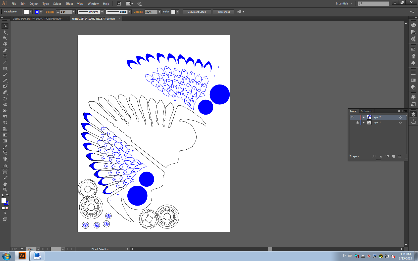
The engraved portions are shown in blue. These paths were then imported into EngraveLab and set for lower power/higher speed to get the etching effect necessary for detail work. A breakdown of the construction of the wings is shown below:
With a large amount of CAD under my belt, I then proceeded to the laser cutter. Unfortunately, the troubles weren’t quite complete, and both Marie and I faced issues in actually laser cutting. Our biggest issue, surprisingly, was in finding the correct speed/power settings necessary to cut all the way through the wood without burning it. We attributed much of these difficulties to attempting to cut bowed wood, which would negatively impact the focus of the laser cutter and cause issues cutting all the way through material in the bed.
In addition, we helped Carlos discover a flaw in the laser cutter’s datum/z-axis adjustment (read: we broke it accidentally, and luckily Carlos fixed it): if the laser cutter attempts to calibrate itself and misses, hitting the bed instead. However, it will not read as having hit anything, and will continue raising the bed into itself in an attempt to intersect the bed with the sensor. In addition to creating a horrible sound, this no doubt causes damage to the laser cutter, and cannot be stopped without some finagling of the limit switches on the upper portions of the laser cutter.
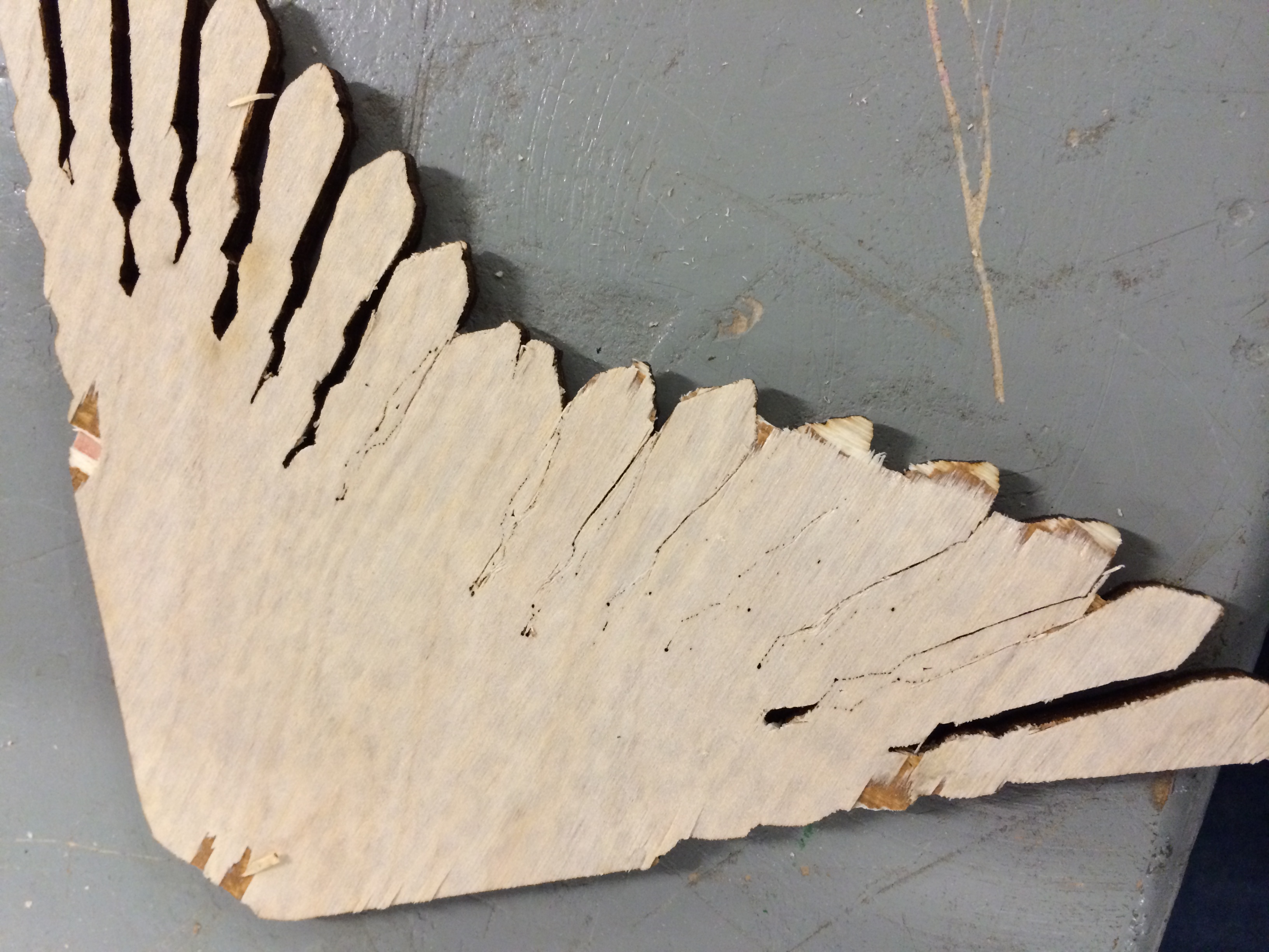
The tail proved to be the hardest portion of the owl to cut, as the intricate engrave work and the narrow cuts necessary to create the bottom feathers were difficult for the laser cutter to contour. We actually had to cut this piece three times before creating a viable piece: the first time, the laser cutter failed to cut all the way through the wood, leaving the tail stuck in the material; the second time (shown below), the laser cutter again failed to cut all the way through the material, leaving chunks of excess wood clumped around the feathers. Because of the long time spent engraving the rest of the piece, re-cutting the tail each time was a time-consuming process.
In addition, we had to adjust the settings for the engraving. Our initial settings were again too strong, causing the engraving to burn through the wood.
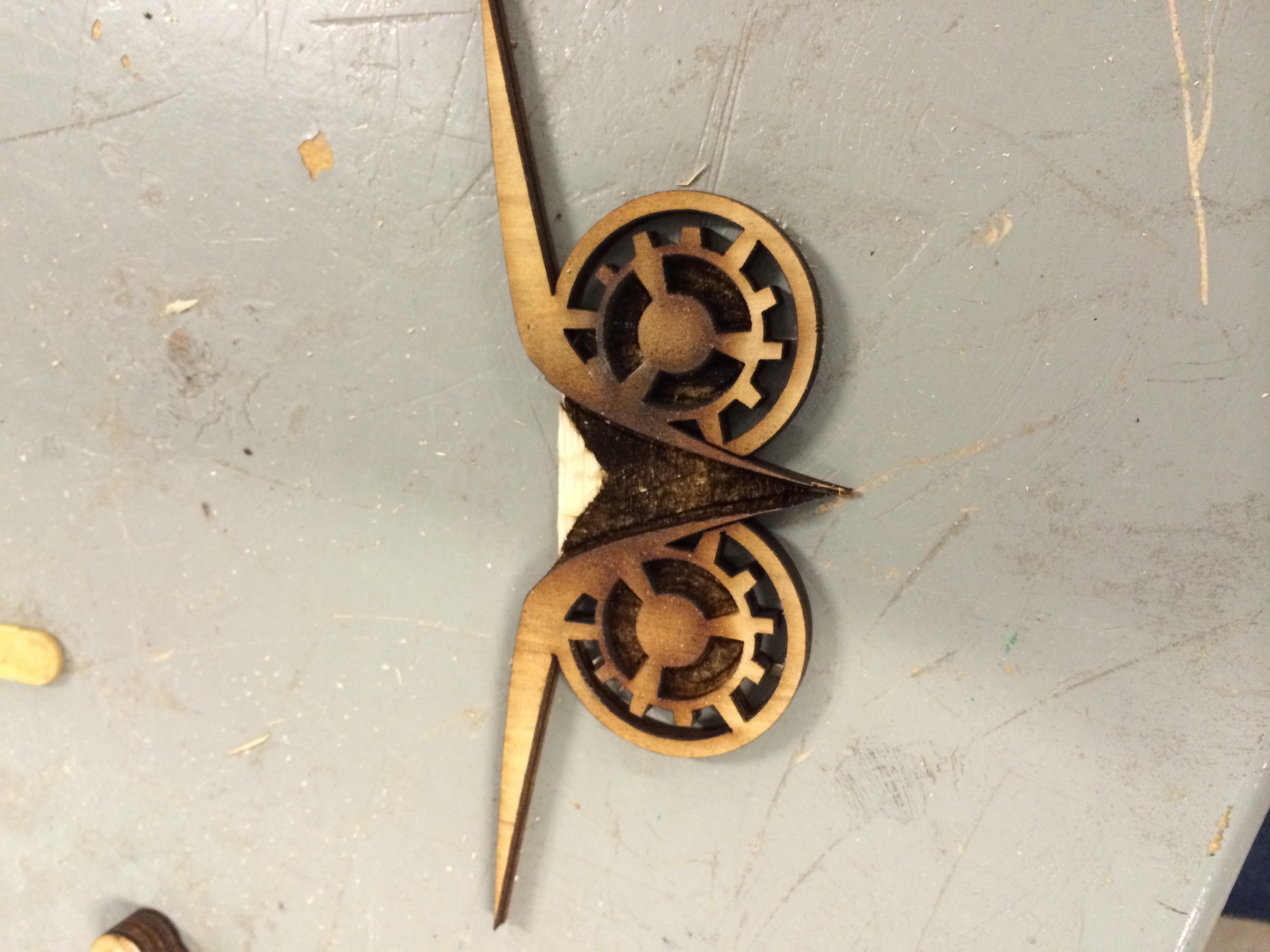
After the difficulties with the initial cuts, we were able to use the laser cutter to great success. We found that the laser cutter is capable of creating extremely intricate, detailed, and precise cuts at an extraordinarily fast rate, allowing for an astonishing array of aesthetic details to be added in at the last minute:
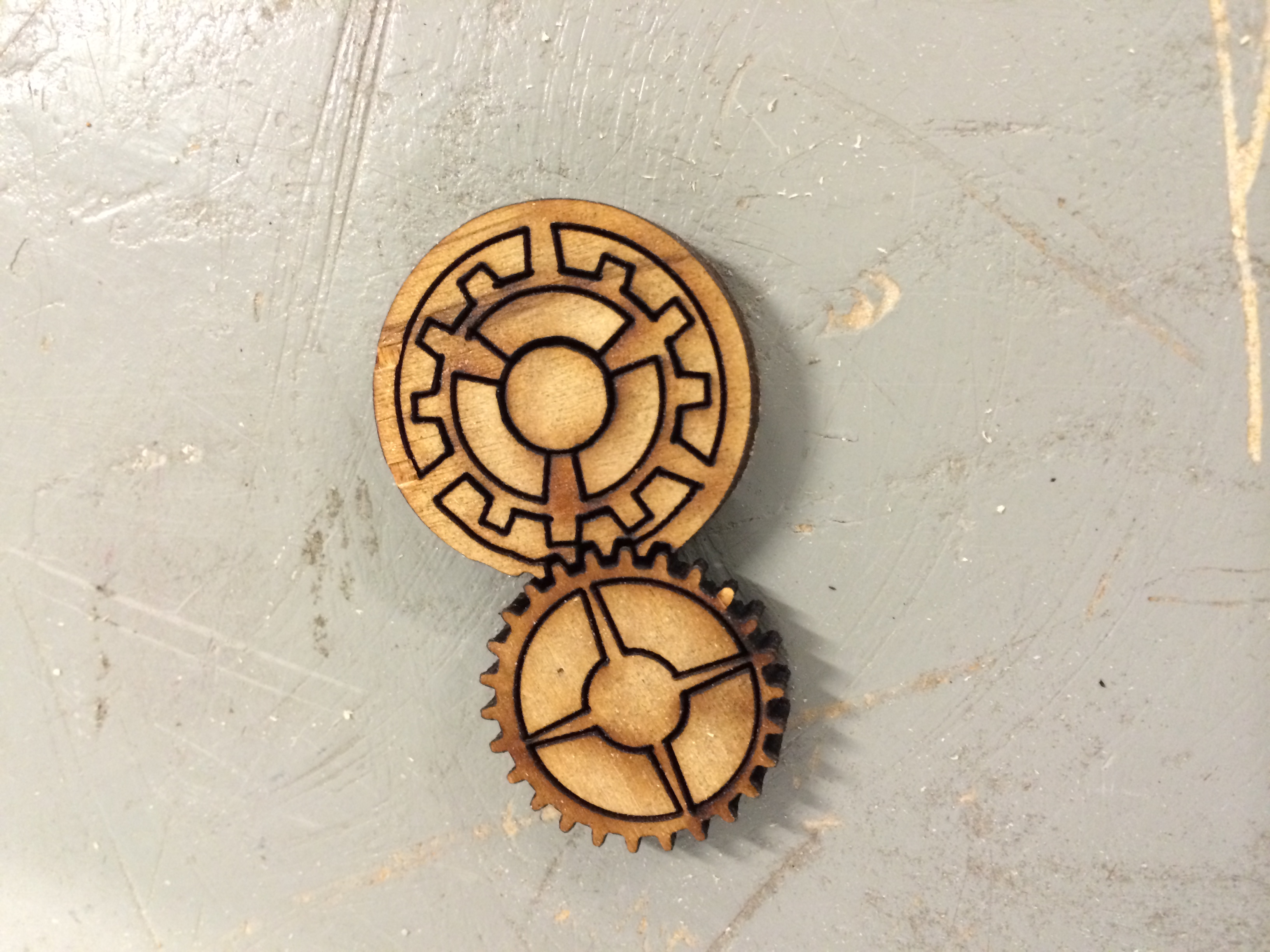
Note that the above gears are approximately one Mikaela’s thumb width (thumb not shown).
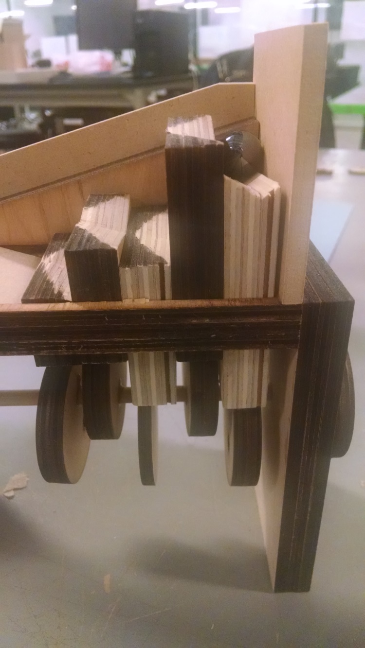
We were then able to assemble the pieces into a final product using dowels (3/16 inch) and wood glue. An in-progress image of construction is shown:
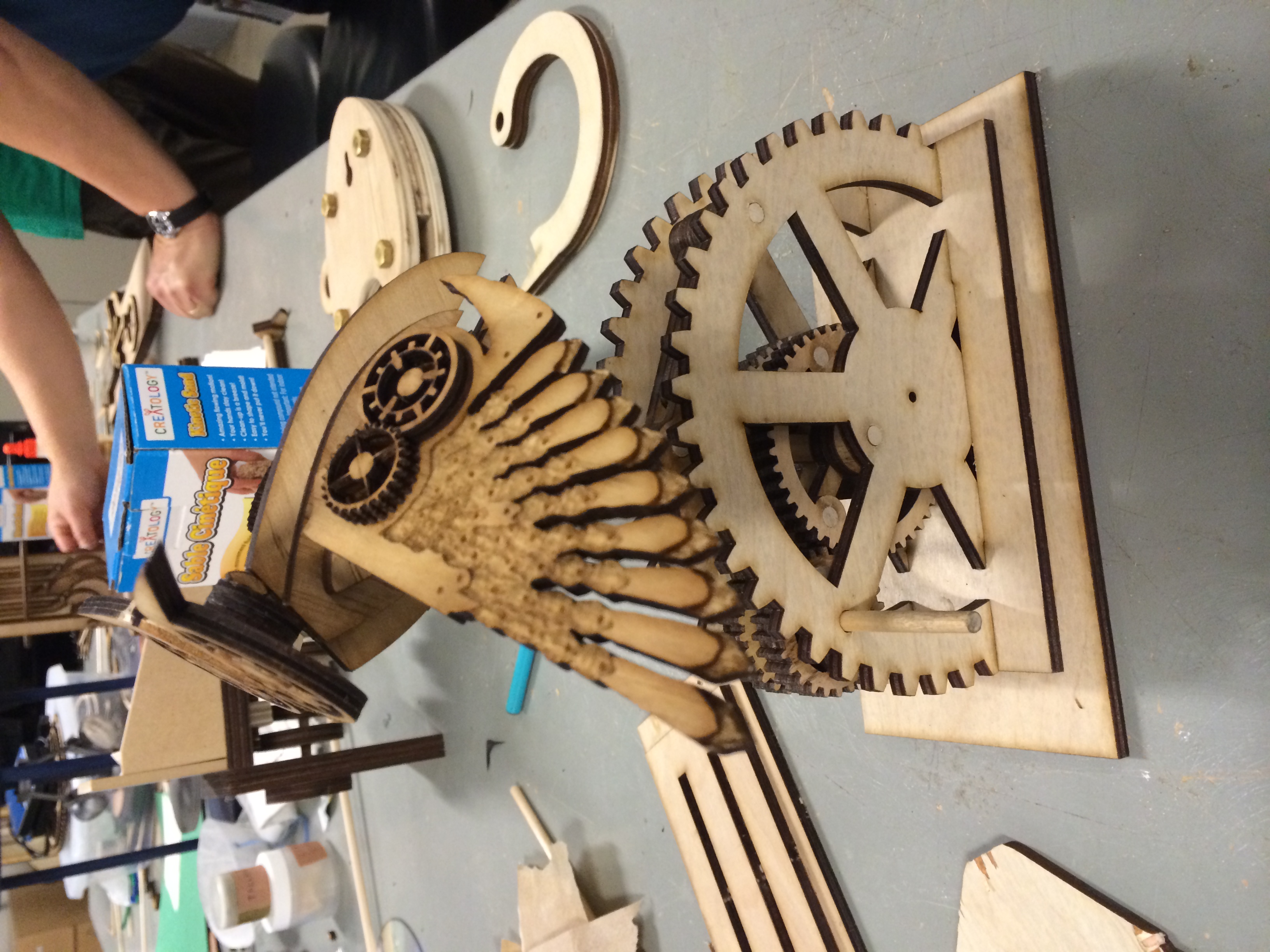
Note that the tail provides counterweight to the head and the front half of the owl; the extra weight of the tail allows the owl to rotate more smoothly.
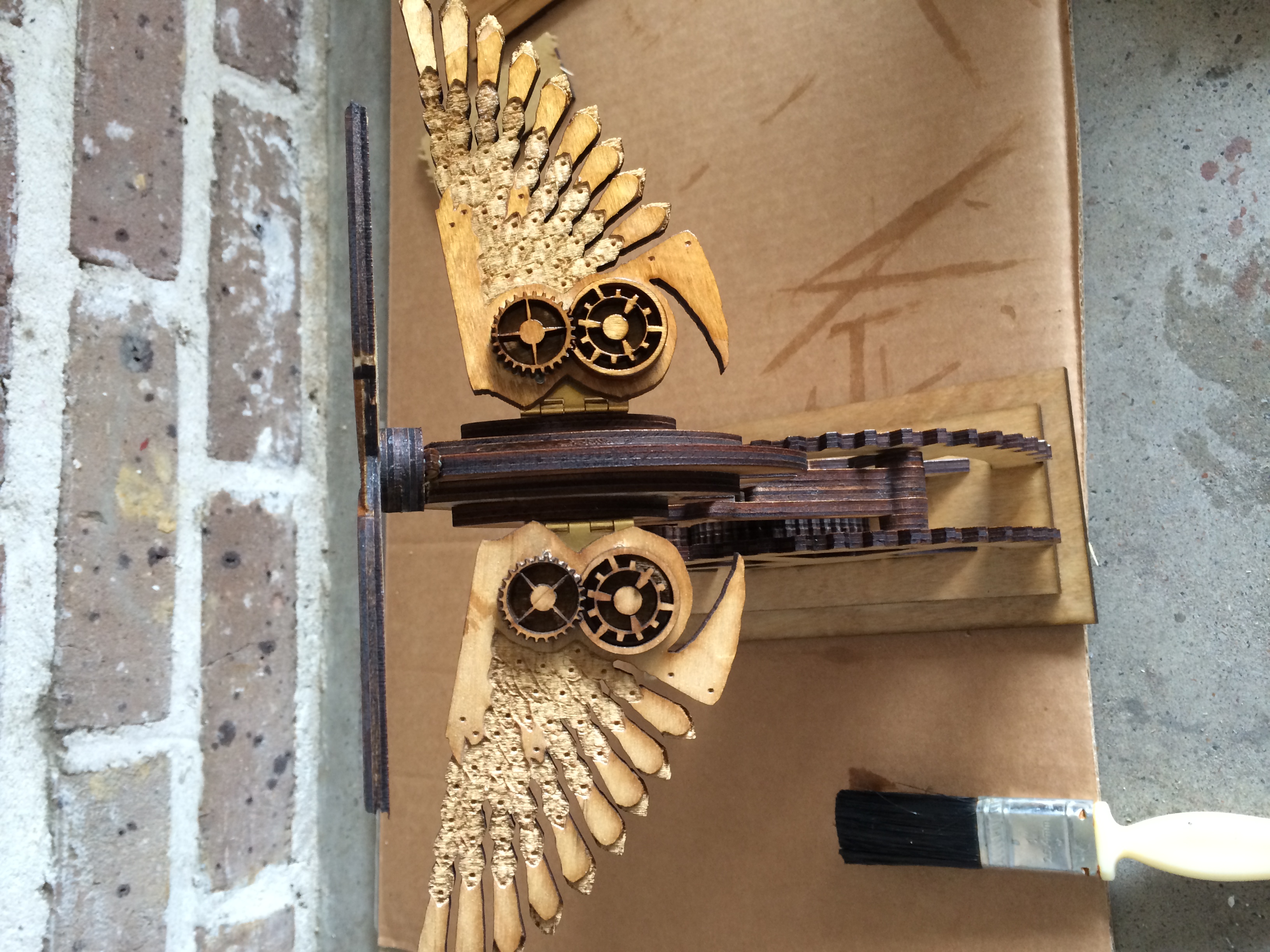
After assembly (in the future, we understand that this step should take place prior to assembly), we used lacquer to give the owl a darker, more polished finish. An in-progress image of the lacquering is shown below. The right wing has been lacquered, while the left wing has not.
A final video of the working solution is shown in the link. Success!
http://engi210.blogs.rice.edu/files/2015/03/IMG_0419.mov
