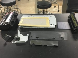
When Kelsi and I first got this printer, we started attacking on it right away. It was massive, heavy, and also had tons and tons of components. By the time I finished taking it apart, the list of components (that we had successfully pried open) was three pages long: 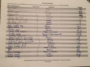


The tools that we had used to disassemble the machine include one flathead screwdriver, and two Philips screwdriver (one shorter than the other because certain spaces were too tight for the longer screwdriver to fit).
There were a few components of this printer that I really liked. One of them was these unassuming hoop: 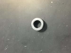 I’d found two of these hoops, and their sole purpose was to combat cable clutter. The complicated bundle of cables in the printers were held together by this little hoop, and the cables (which were all joined together at the end by a little plastic part), were securely fastened through this hoop as you had to angle the plastic part in a very deliberate manner in order to untangle the cables from the hoop, hence, it was very effective in its missions. The hoop is clearly made from metal, probably an alloy. Given that there are several ways to make metal hoops, I would guess one of the ways that this could have been made would be through metal rolling.
Another component that I’d found belongs to this family of plastic materials. They mostly act as snap joints and possess a certain degree of flexibility (though varying), some were deliberately made that way to hold a certain component in place but meant to be removable, while others were held in place very tightly.
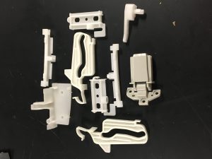 Given that plastics are very commonly made through injection molding, I would assume that most of these products were made via that process, especially given their specific design and shape.
 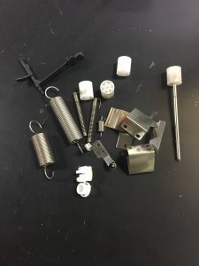 Another component which was very common in the printer were these springs of varying shapes and diameters (seen above). Like the plastics, they were often used to hold things in place but meant to be removed/flexible. Given previous knowledge that springs are usually made from steel, I’d guess that some form of machine with different temperatures is involved in the manufacturing. According to this resource, coiling is a way to make springs!
A few features of the machine including the lid of the scanner, as well as the lid of the printer itself. These were both held together by a hinge at the end, as there was no spring mechanism involved. The former allows you to put things on the scanner and close it shut while the document is being scanned, while the latter allows you to take a look into the machine and change the cartridge. The disassembled lids can be seen in this picture (bottom right):
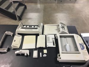 Another thing which was main design feature of the printer was the numerous amount of covers it had which combined as the printer’s casing (seen in picture above). The different covers of the printer were made of the same plastic material, and were taken from all sides of the printer, as well as from the inner components. My guess is that plastic was the primary choice of material given its lightness, as the other components the casing held were already pretty heavy. Plastic satisfies the mission of the casing as something durable and tough, yet light at the same time.
There were also several circuit boards in the printer. These PCBs were probably manufactured in the company that produced the printers, or outsourced to a different company that specializes in PCBs. After rummaging around I found this website which explains the process in detail. The number of PCBs in this printer came as a surprise to me initially, but made sense after you take into account how many functions the printer has and the different machines needed to operate in this space. 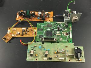 Looking back into the disassembling process, we discovered that the machine was assembled using several different kinds of fasteners, as well as snap joints (as pictured previously). We had to use both screwdrivers and our hands to be able to take the entire machine apart. The fasteners were mostly Philips screws, though of varying sizes and length. One thing I didn’t understand though, was why the same exact screw had different colors. My guess would be that it was color coded to enable the assembling process easier, both of interior and exterior components.
 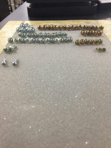 Some of the components (such as the screws) were definitely made out of off-the-shelf, but I would say that most of the components of the printer were made specifically for itself. Simple things such as the foam board had to be cut to this exact dimension to fit the scanner bed, while more complicated things like the casings, snap joints, and springs were made to dimension for this printer. Not forgetting more complicated components like the rollers, the printer head, etc.
I believe that the machine was never designed to be taken apart and put back together, given the complexity of the machine, as well as the difficult process one had to go through to be able to actually take it apart. It was built very sturdily and several components were held very securely together. This led me to believe that the machine was meant to be discarded after use, which is the case for most technology products nowadays. Companies and manufacturers no longer design for things to be used for several decades as they need to keep up with the changing times, hence why bother to build something that can be fixed so as to be used over and over again? Some of the components could be recycled, but in order to do that you will have to take the entire thing apart, and sort them into their respective materials to be able to actually recycle the entire thing. Again, as mentioned before, this is a long and tedious process, hence leading me to believe that the machine was not produced with the intention of it having to be recycled at the end of its life cycle. My conclusion from this lab is that several products in today’s era are built and manufactured in a specific way, made efficient only through assembly lines and machines (they would be way too time consuming for humans to build).
