This week, we disassembled an old scanner during class. Despite the simple function of scanners, there were a surprising amount of components involved.
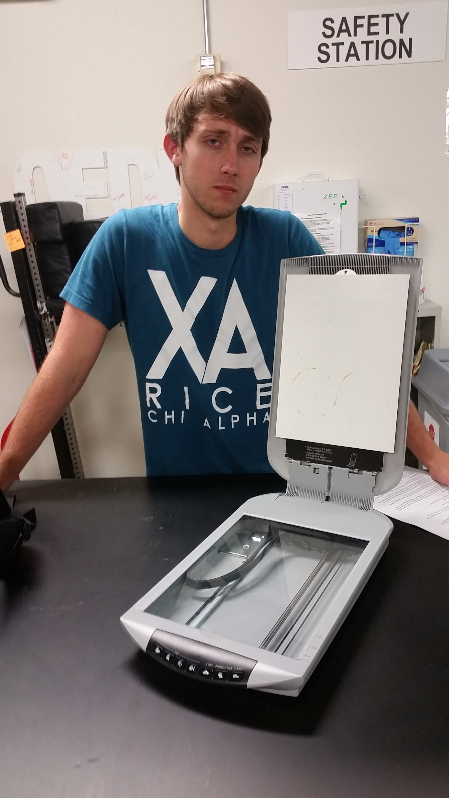
Figure 1: Scanner Pre-deconstruction
As we started to take the scanner apart, we quickly realized that this device was not originally built with the intention of quick deconstruction. I would think that they would have made access to key components much easier than it was, but almost everything was hard to access. I assume that this particular scanner was meant to be thrown out when a component stopped working.
As you can see in Figure 1, the scanner does not seem to have many components. However, there are many components that are below the glass and hidden from view.
There were only three screws visible (that did not really help us take the cover off), which quickly led us to believe that this product was not meant to be disassembled. After sliding the protective paper sheet off of the underside of the cover, we still did not find any more screws. However, after we peeled off some glued padding and extra paper, we found screws that allowed us to take off the cover of the scanner and take it apart. The glue was another indication that this device was not intended for deconstruction, as glue is a one-time attachment method and cannot be reattached easily.
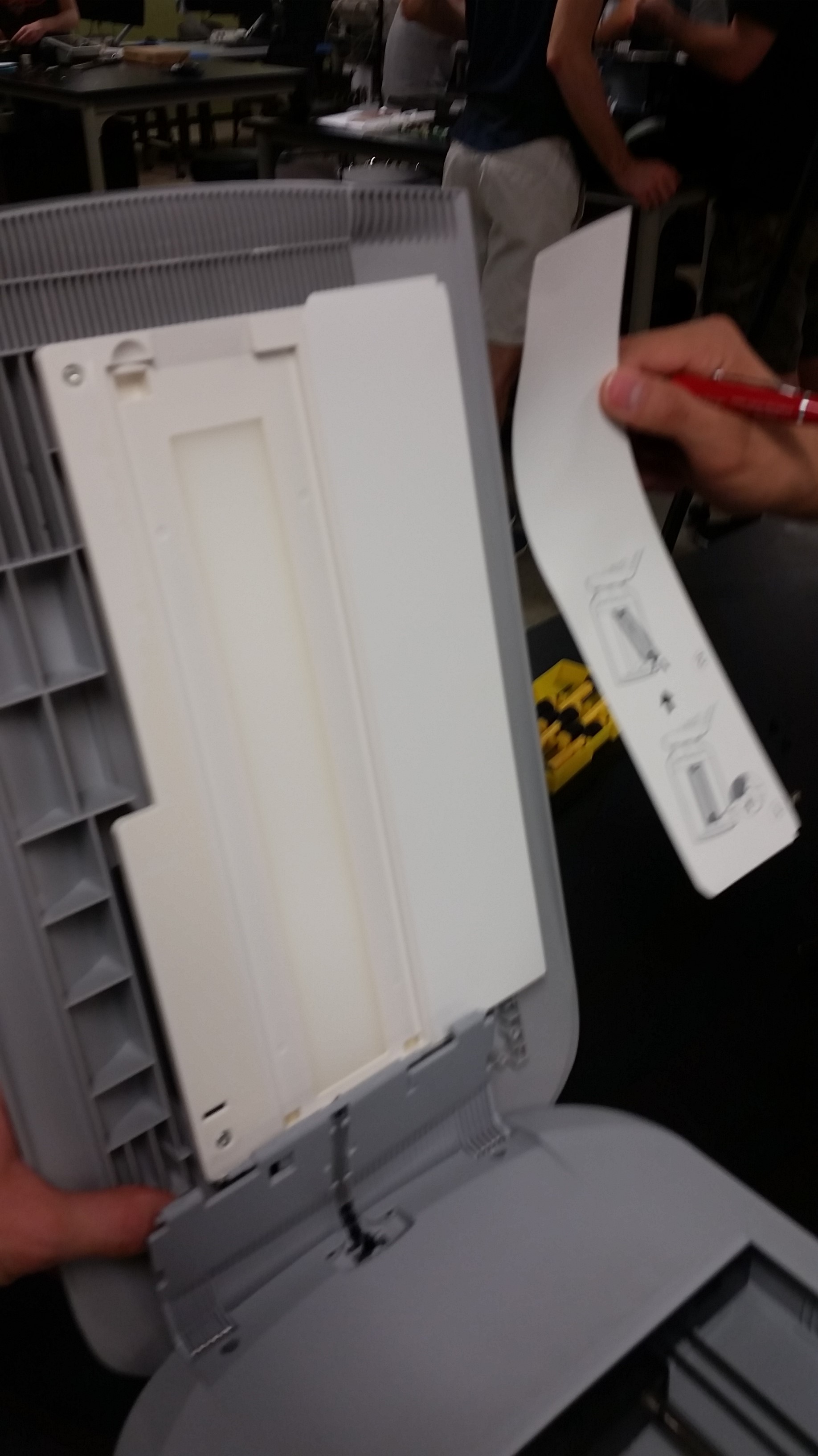
Figure 3: Glued components reveal screws underneath

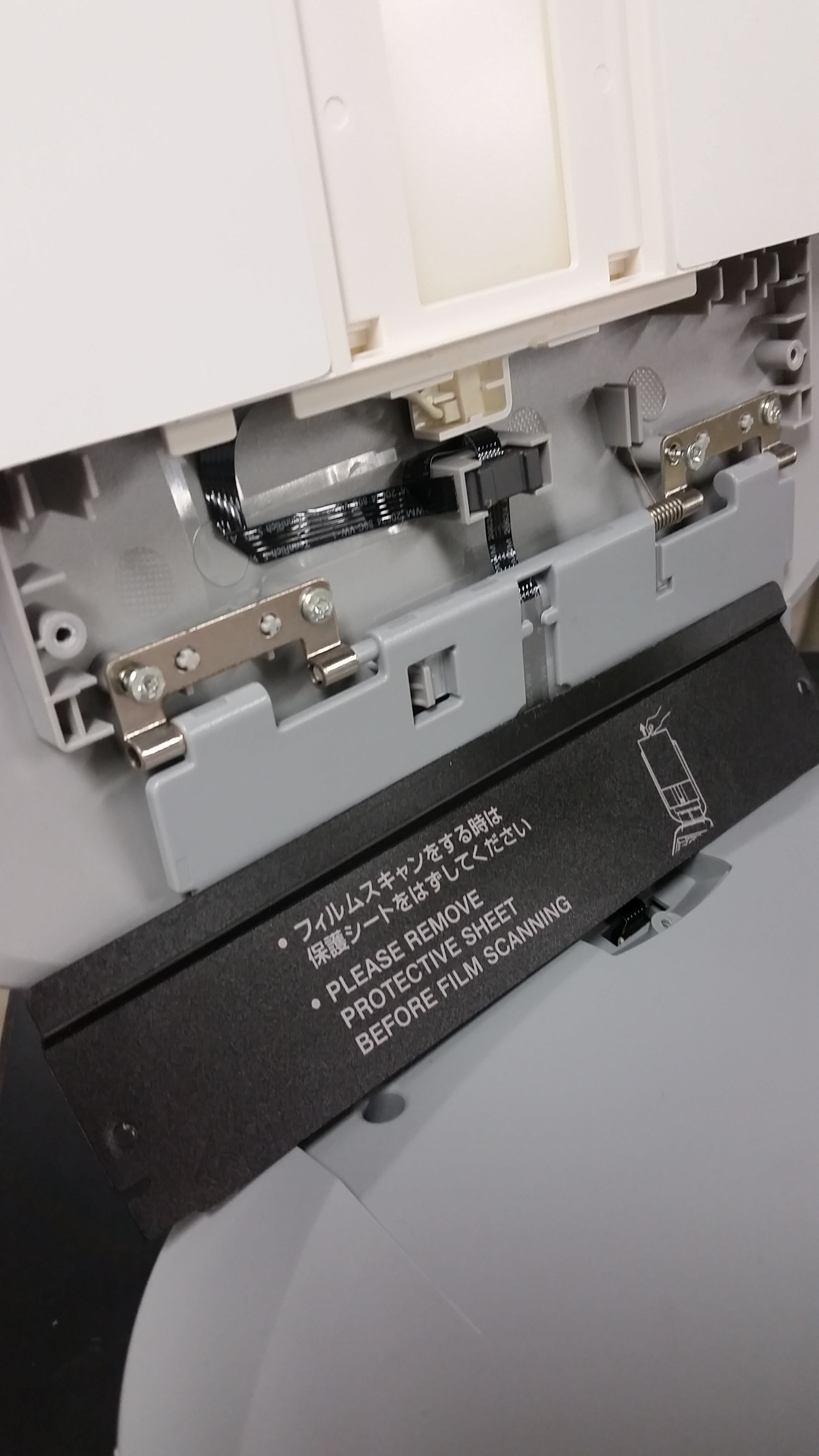
Figure 3: Hinge screws found behind glued component
After removing the glued sections above, we were able to unscrew and detach the cover as well as the backlight assembly. The backlight assembly was surprisingly quick to disassemble, as it was easy to detach from the cover and was held together only by screws. It makes sense that this component would be easy to disassemble, because one may want to replace the lightbulb. However, it does not make sense that we had to remove glued material in order to get to the backlight assembly.
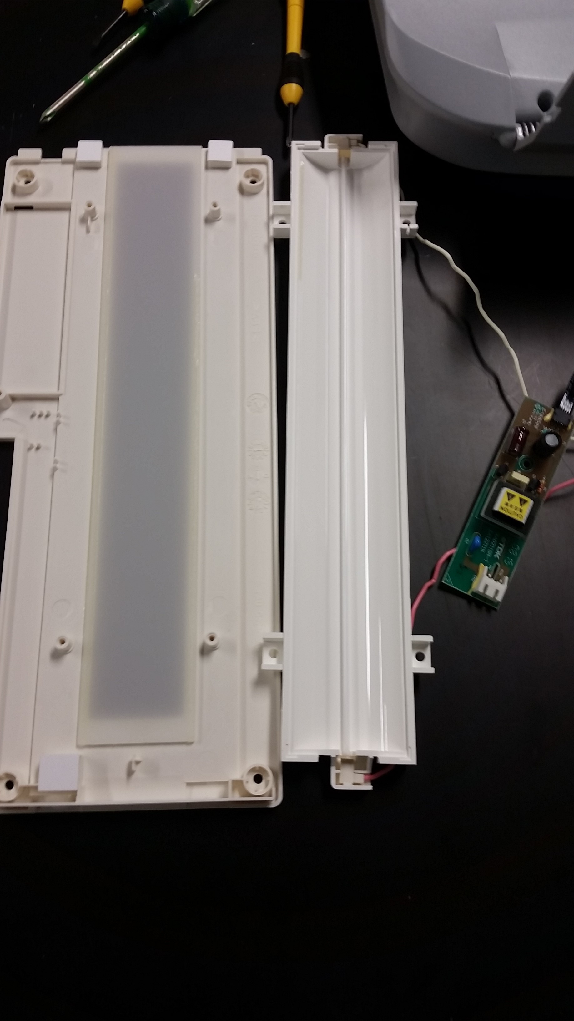
Figure 4: Backlight Assembly
Up until now, the cover was made using traditional fasteners like screws and glue. However, the main housing used snap joints around the perimeter to encase the inner components. We used a medium-sized flathead screwdriver to lever the snap joints out. Once the main housing was off, we noticed that the glass bottom was glued to the upper part of the plastic housing.
Despite the design flaws in the cover, the main assembly seemed like it was made to be disassembled. Nothing used glue except for the expensive optical components of the translating scanner assembly. It made sense that these were glued in, as the manufacturer probably does not want these components moving around in the slightest, or else the whole device would lose its entire function.
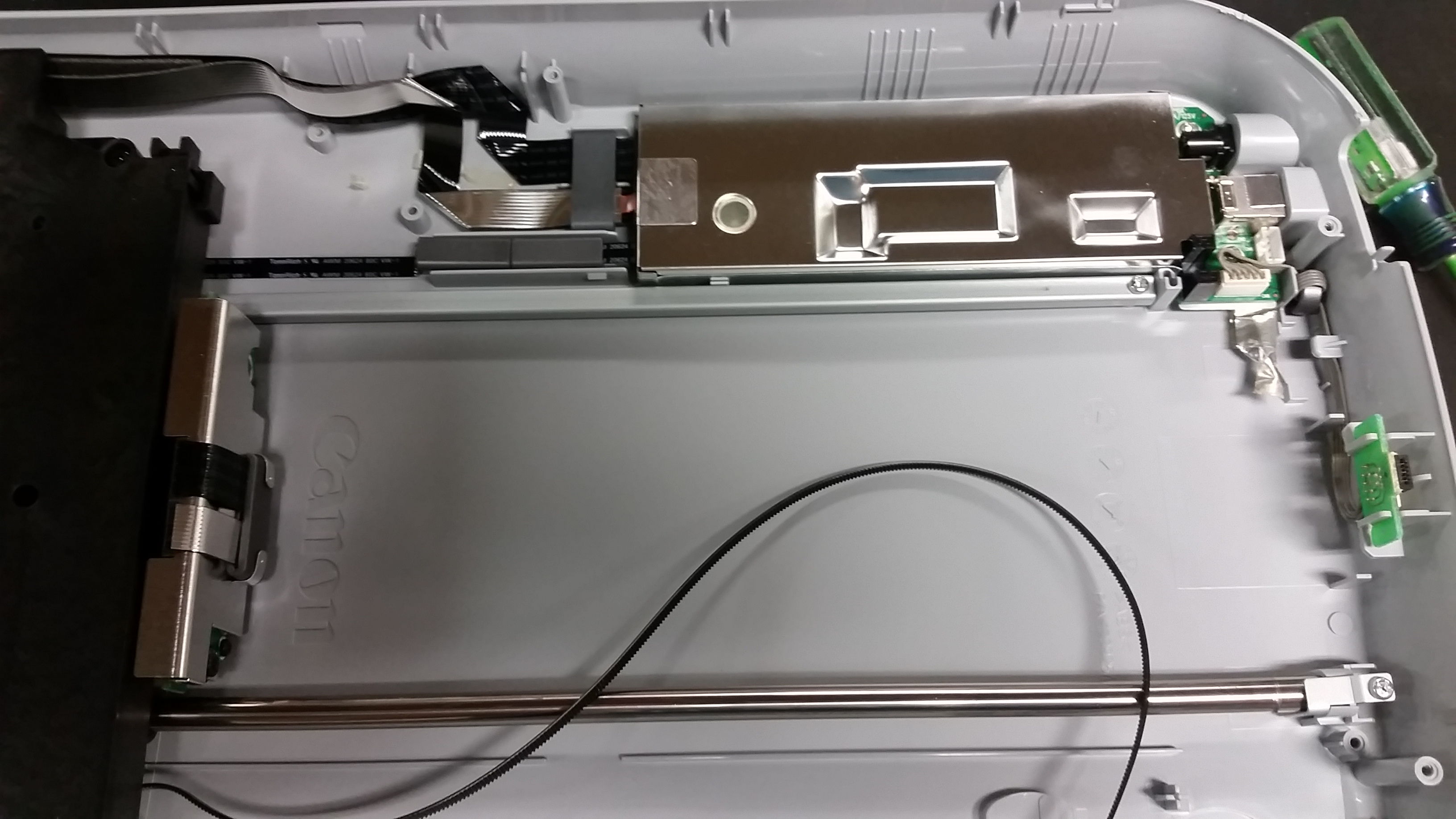
Figure 5: Main housing assembly
We were able to pull out all the components and strip the main housing down to plastic, save for the buttons on the front (attached by screws that were impossible to reach). Almost all the hardware within this assembly can be replaced due to its ability to be taken apart. Also, since the majority of the components are located here in the main assembly, I believe that the company did build this device to be deconstructed in this section (but not the cover, as discussed above).
However, the silver EMI shield in Figure 5 proved to be difficult to pull off the housing until we found the hidden screw. We found the screw underneath a thick circular plastic cover sticker, and we assumed that this was used to prevent EMI outages through the screw hole. This further corroborates the theory that this main assembly was meant to be disassembled, because if it wasn’t, they would not have bothered leaving a hole in the EMI shield.
Summary:
Many of the fasteners were traditional, using screws and glue. However, the main assembly disconnected using snap joints. The traditional fasteners seemed to be off-the-shelf items, while the snap joints were designed into the housing. The fasteners made up a very small percentage of the weight of the system, with injected molded parts making up the majority of the weight. Glass and optical components also took up a good deal of the weight of the product. There were also a few stamped parts as well, which consisted of a rack mount (you could tell it was formed from a sheet of metal), and the EMI shield.
This product might be able to be recycled if all the electrical components are stripped. Also, the parts that were not meant to be deconstructed (glued components) needed to be separated from the material anyways.
I learned that it may be challenging to manufacture/design a system that is easily disassembled. Also, manufacturers will often use methods that are cheapest (such as glue), even though they may not be easily taken apart. Snap joints, although convenient for disassembly, may increase the manufacturing cost and may sacrifice structural rigidity. In sum, some components of our device were definitely not meant to be disassembled (cover), while the main components were easily accessible and removable (components in the main assembly). Also, we did not use any complex tools nor did we end up with many components at the end, which led us to believe that this was a relatively simple product to disassemble.
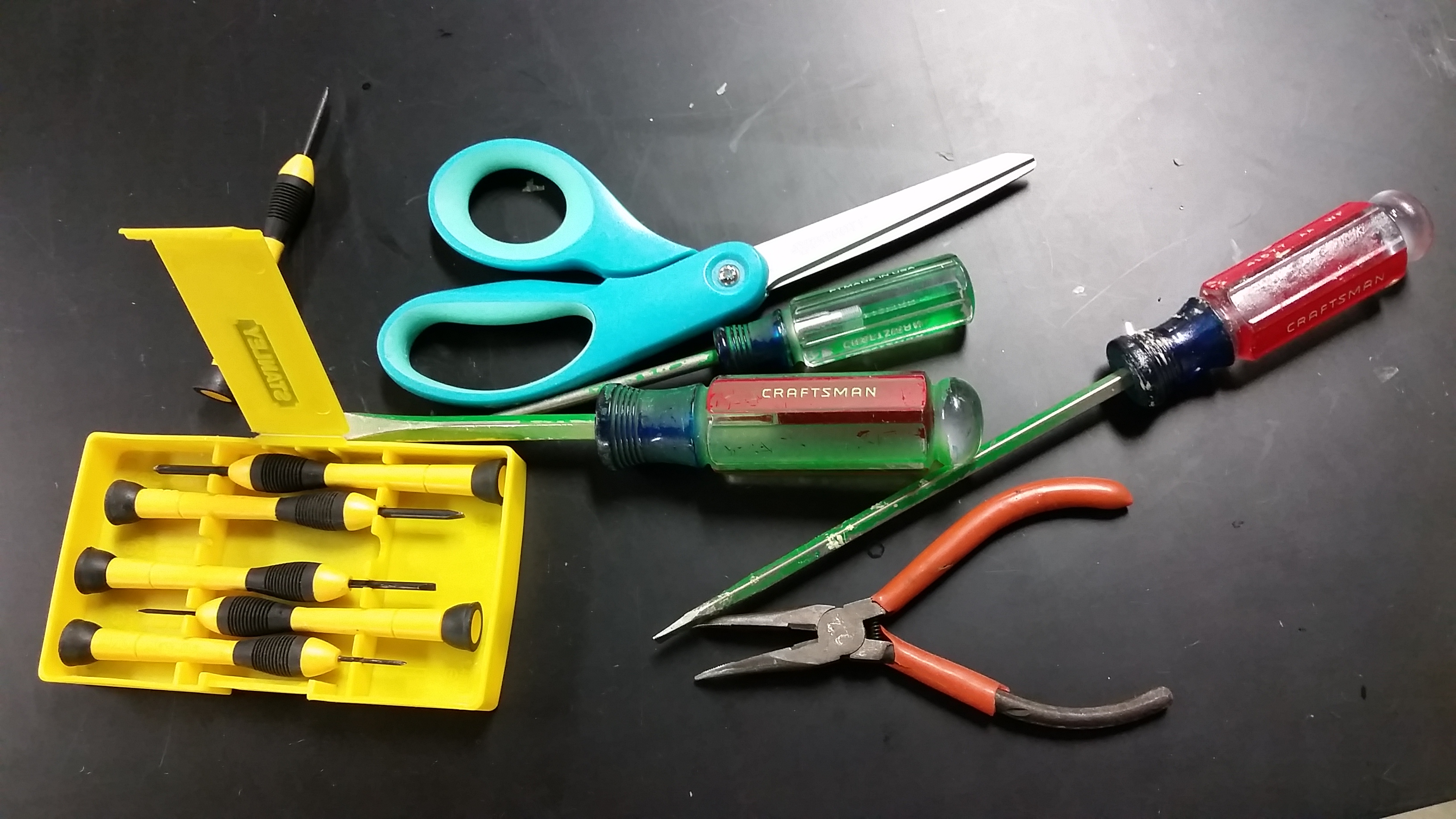
Figure 6: Tools used in disassembly
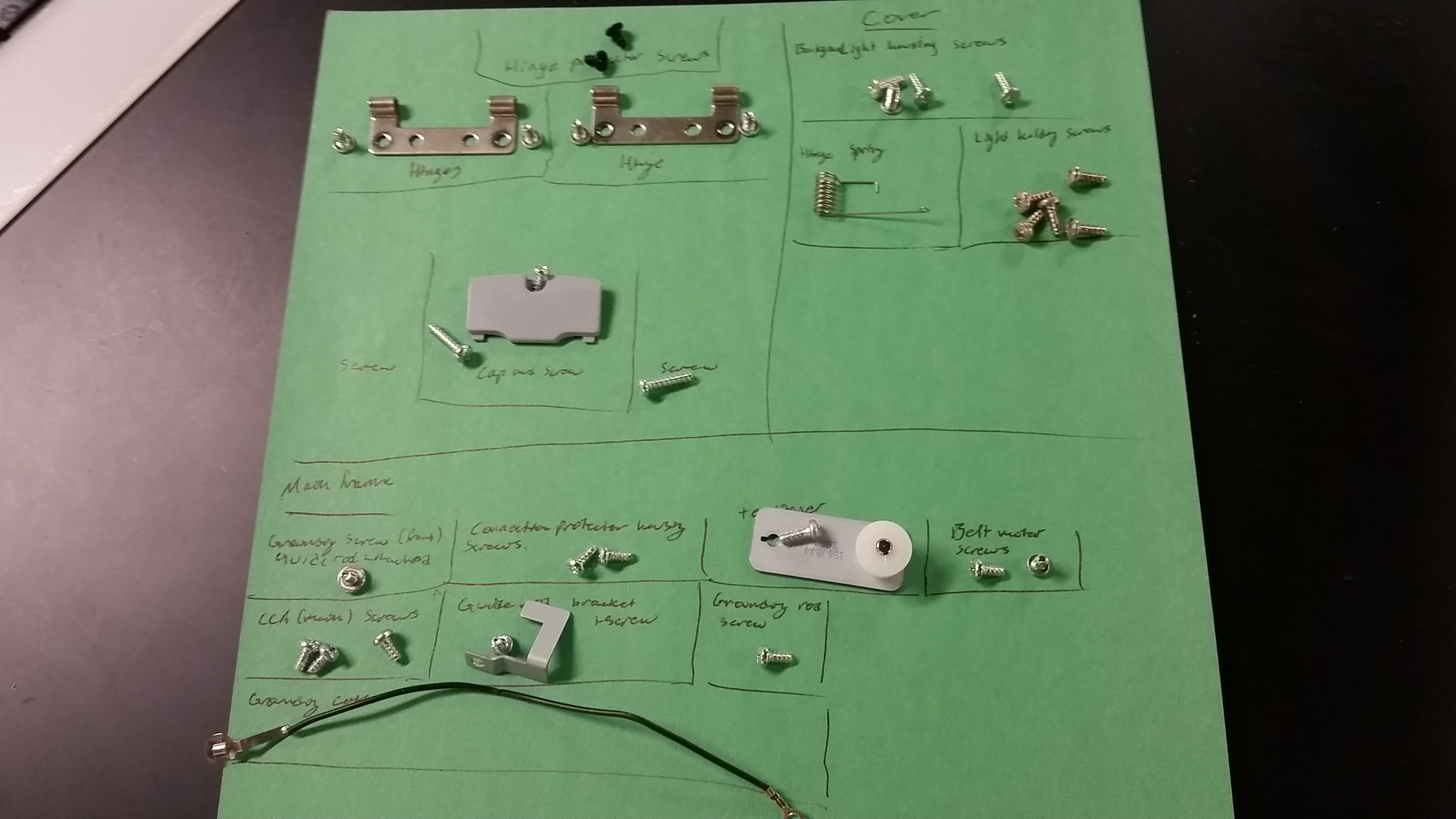
Figure 7: Fasteners and simple components
