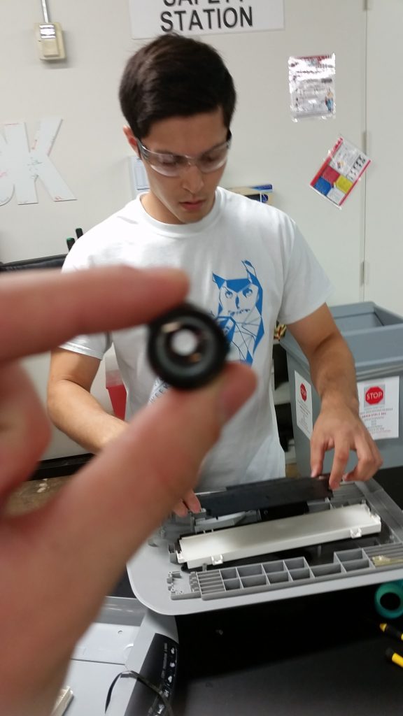
The Beginning

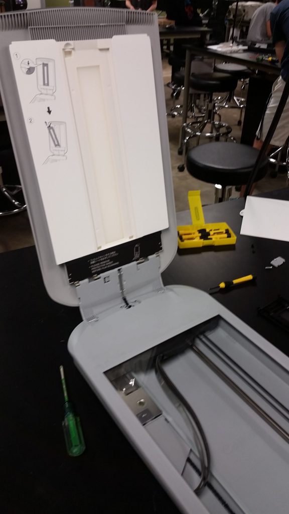
To start off the process, we first documented what our device was, what it did, and what we though our best avenue of approach to assembly would be. As you can see, we started with a document scanner, one with a relatively sleek design and no initially clear disassembly points. Given the sleek, well contained nature of the device, it suggests that disassembly was planned to be infrequent, as style and simplicity often comes at the cost of ease of disassembly. However, by inspecting the device, we were able to plan our route of attack. The scanner feature two main components: a large, glass covered scanning bottom, and a light producing top. Connecting the two is a small hinge, and here we saw the first sign of fasteners that could be removed.

Separating the two halves
Beginning with the one visible screw, we began taking the machine apart. Past the first screw, which only removed a small plastic cover, we were again stumped. This is the point at which I realized that our item was likely never meant to be disassembled or fixed whatsoever, as no provisions were made to guide us towards disassembly points, and in fact disassembly was frequently blocked by glued coverings.
We soon found that a piece of black plastic/paper was hiding hinges with screwed connections, and these were removed in short order. Only one side of the hinges was metal, connected to molded plastic, which leads me to believe that the stamped pieces of metal were designed and produced for this item specifically, and are not off the shelf. This can be seen below.
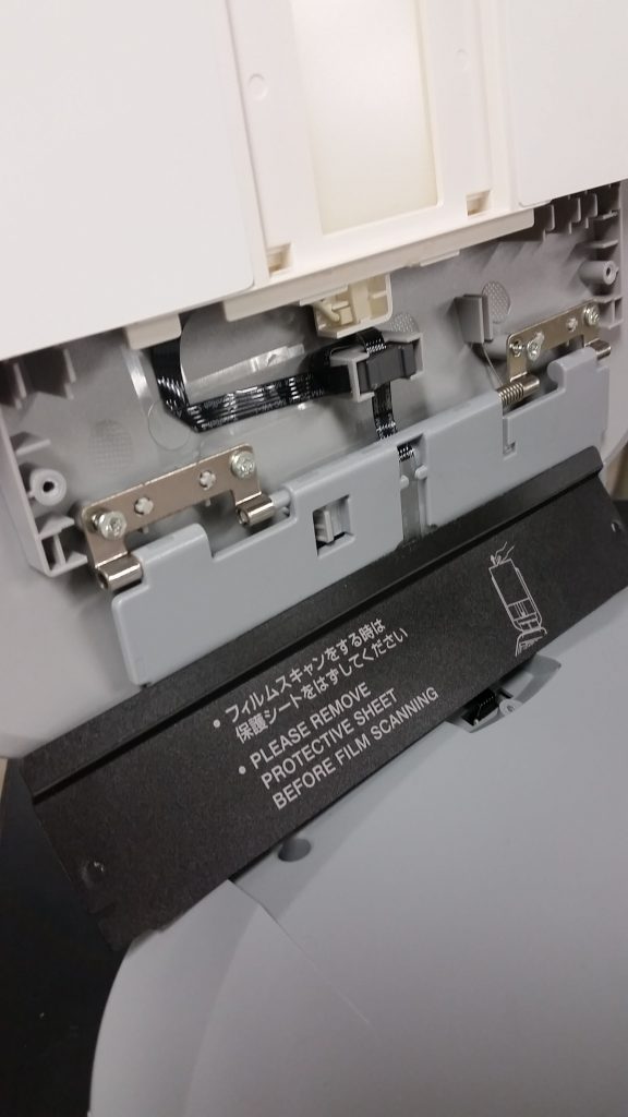
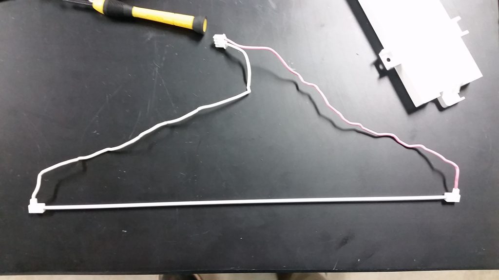
At this point, the two halves were essentially separate, minus a collection of wires connecting the two halves that could not be immediately separated.
Disassembling the light producing component
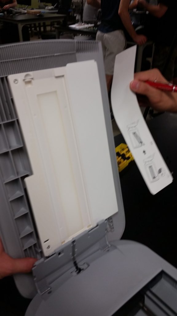
We will now refer to this component as the ‘top’ of the scanner. Here, we first had to remove a protective paper cover, revealing instructions printed beneath. This implies that the protective cover was indeed meant to be removed, which is logical, as it reveals and protects the light producing fixture on the top. Once this was done, paper and foam pieces with use instructions had to be peeled off, revealing more screwed connections, but connections that were never meant to see the light of day.
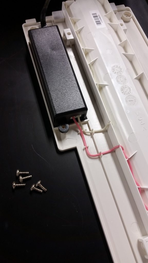
Once removed, the entire lighting assembly lifted out, revealing a black box containing the electronics for this subsystem. This too was screwed in, but with a latch on one side and a screw on the other, which likely saved on cost by removing a single screwed connection. In addition, the wiring here was retained by little nubs cast into the plastic, as compared to glue which was used elsewhere in the device.
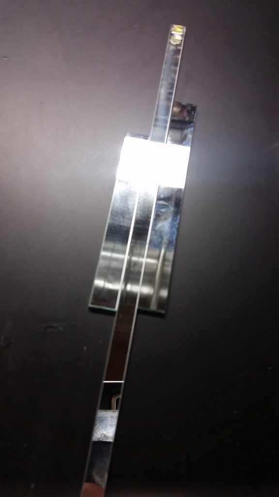
Full disassembly of the lightbulb fixture, which involved breaking glued connections, revealed all of the components making up the top.
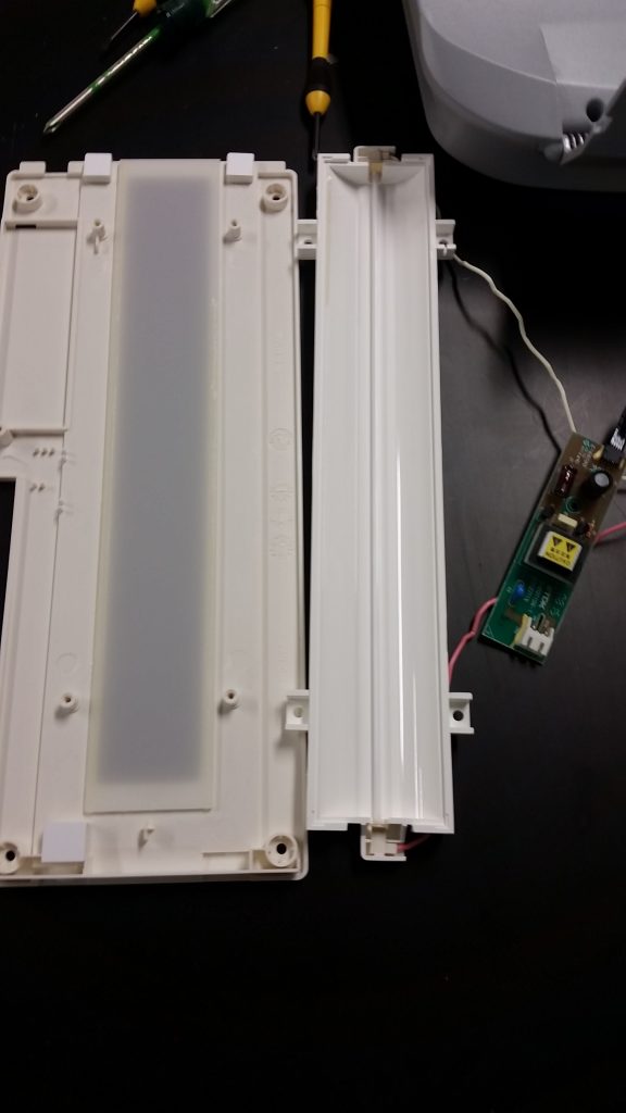
Below the separated lightbulb can be seen, which is much thinner than expected. At this point, the top was fully disassembled.
Disassembling the scanning portion
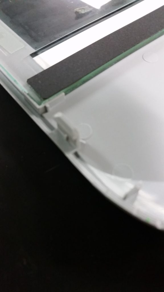
This section will now be referred to as the ‘bottom.’ This portion offered no easy access, with a glass covering and mysteriously connected lower molded plastic portions. Using a screwdriver, we were able to pry the plastic seam apart until we were rewarded with a resounding pop, revealing one way plastic snap connections, once again clearly never meant to be undone.
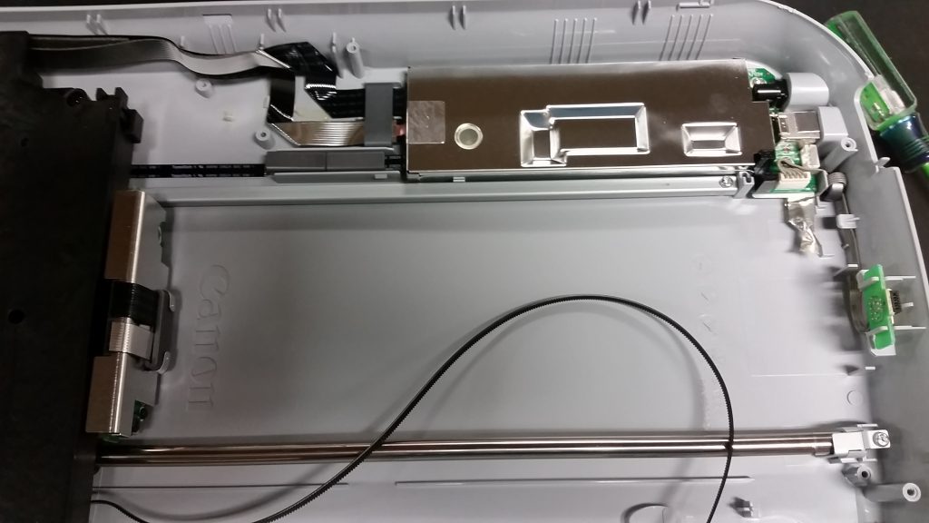
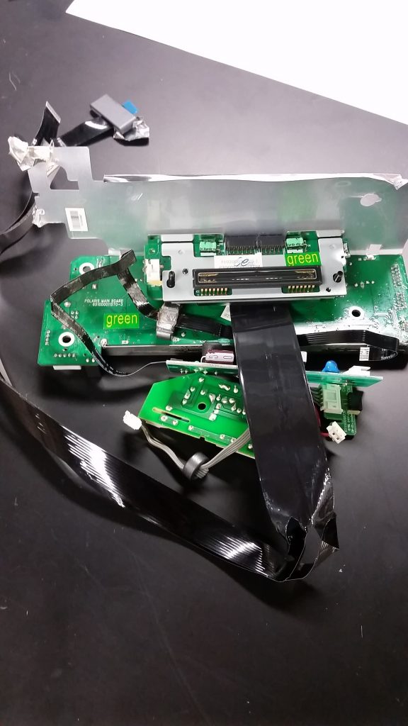
Having done so, we revealed numerous connections that could be undone. Nothing terribly exciting in terms of assembly was revealed here (nothing that was not revealed before, I should say) and so I have provided a sample picture below, documenting this process visually.
One different was in purposely concealed connections, such as the masked screw hole shown below. Rather than being a visual block, however, I believe this was done simply to keep contaminants out of sensitive electronics, and interesting consideration for assembly.

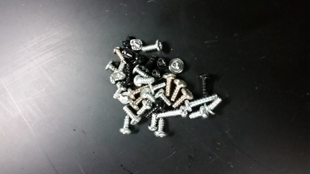
Once the bottom was fully disassembled, our process and exercise was over. We first organized many of the components, seen below.
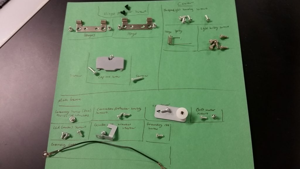
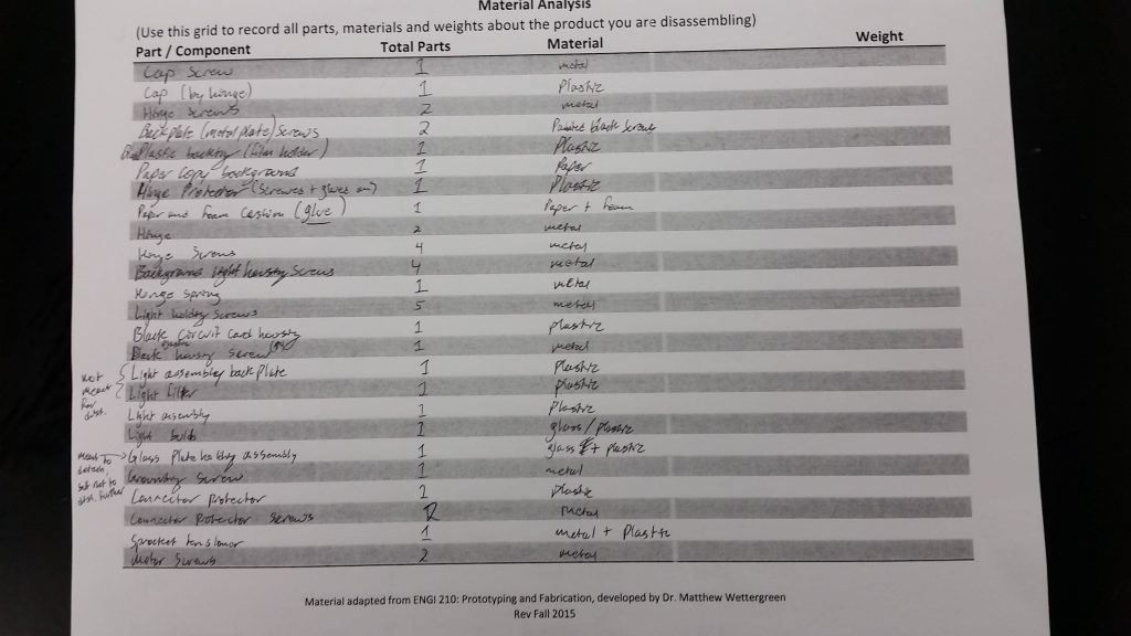
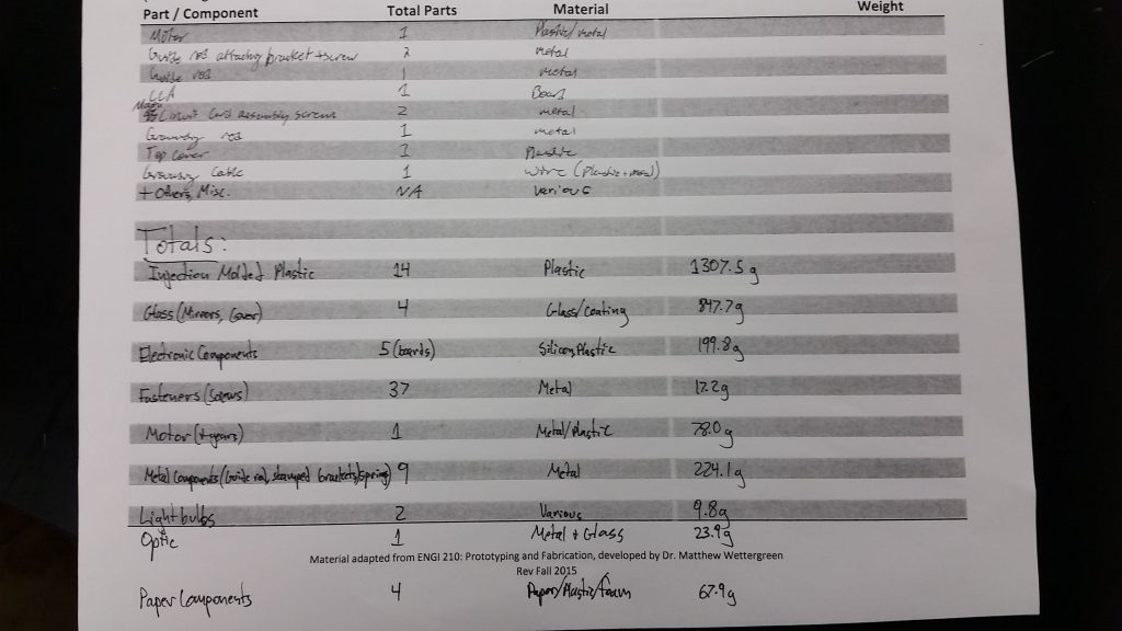
We then grouped items by various classifications, and weighed each component group.

Conclusion
To reiterate the points discussed above, my major realization is that this device was never intended to be disassembled at all, given that one single screw (which hardly attached anything) was the only immediately visible assembly feature. This machine was almost certainly intended to be thrown away if any part gave out, rather than being fixed. That said, there are numerous assembly design features employed in its construction, including reversible ones, as well as traditional fasteners. These included screws, glue, snap connections, and fitted slots/grooves that use friction to retain components. Almost every component appeared to be designed uniquely for this device, though many pieces appeared to be produced in different ways. For instance, there were both machined and stamped metal parts, sheet glass and optical glass, glass mirrors and paper mirrors. All plastic pieces appeared injection molded.
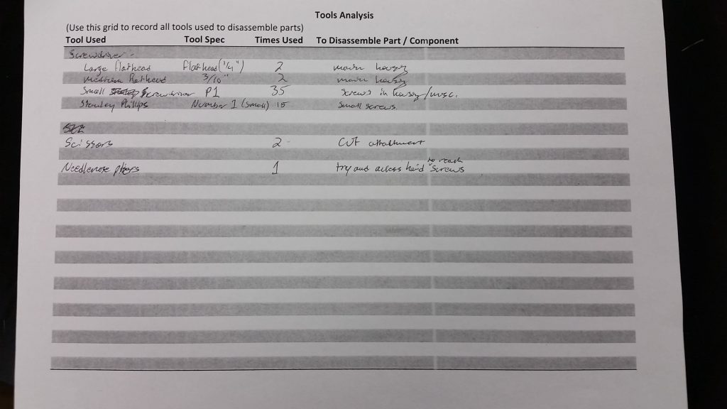
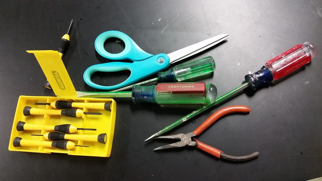
In addition, the way in which different components were permanently affixed, either with out of reach screws or with glue imply that the device was not meant to be recycled, as deconstruction remains nearly impossible even if one does not care about device integrity. One other point of note was the discovery of instruction printed on pcbs (or identifying numbers at the very least), likely for assisting in guiding assembly. Below are our tools used for the process:
In conclusion, I had a great time taking the device apart and investigating the various components, as well as the ways in which they were attached, and I look forward to potentially incorporating some of these methods of construction in my future projects.
Below are the pages of the worksheet for the process.