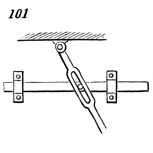
For this week we are supposed to be modeling mechanical forms from the 507 mechanical movement website. My process for tackling this problem will include defining what I need to create, identifying a particular form to create, creating that form followed by documentation.
Step 1: Problem Definition
For this step, I read the rubric to determine what I needed to have as an output for this project. From the project description, I’ve identified three key elements of this project:
- The target of this lab is to create an adobe illustrator file that could theoretically use a laser cutter to cut out a mechanical system model.
- The action of this project is in modeling a machine from the 507 mechanical movements website and model it in adobe illustrator.
- The result of the project should be an adobe illustrator file as well as documentation of my process.
Using these elements I’m able to construct design criteria for selecting a mechanical system:
Constraints:
- Must be able to be modeled in 2D. This means gears that have beveled edges or anything that has defined angles in multiple edges can’t work (I’m adding the assumption that the file will be cut using one pass).
- Must be able to have all elements laser or plasma cut. This means items that use ropes cannot be modeled.
Objectives:
- Must be able to be created by me in adobe illustrator. While this is also a constraint (i.e. if I can’t create it, I can’t complete the project), I believe that if I had infinite time I could create anything. Seeing as how I don’t have infinite time, I need to be able to figure out how to create the object in a relatively limited period of time. Seeing as how I am a beginner to AI, I want to choose a challenging project that I can still figure out how to complete.
Step 2: Selecting the Model
Now that I have set my constraints and objectives, I will select a mechanical movement to model. After looking at the models, I have selected model 101.
Mechanical Movement #101
I have selected this model because it satisfies several criteria. It has several moving parts that are working in 3D levels, allowing me to both use modeling for fitting all the parts together, but a but of creativity as to how one would approach constructing all the parts if you were only using a laser cutter.
Step 3: Modeling
This was a very challenging project for me, not because it was technically difficult, but rather because I ran into technical difficulties. Throughout the course of the time I worked on this, adobe illustrator quit six times and I had to switch three computers because they were frozen. I also had some challenges learning how to utilize tools that we hadn’t covered yet but were helpful to modeling my shape.

To start, I took the image an imported it into AI.
Looking at the shape of the items I mentally broke them down into their component geometries. I built the first object by forming circles and rectangles to form the base of the shape. I then filled in all the shapes and merged them to form a complete solid. See image on the left.
After forming the base of the shape, I created the negative elements by repeating the process for forming the body (i.e. creating the outline by combining geometries, combining all solid geometries by merging) until I had formed a solid shape that was the shape of the negative space on the lever. I then used the “remove all underneath” function to use the negative space shape as a cookie cutter to remove space from the original shape. I then took the shape and created an outline by utilizing the “outer shape” function in object.
From here I had created my first shape. In order to create the other elements of the mechanical movements I needed to repeat some elements of the shape (like top pin). For this purpose I utilized layers. Each element got a different layer so I could move and manipulate each element individually.
 Once I had created all the shapes, I showed all the layers on the final form. I did not create the middle pin that attaches to the orange bar, as that would be a dowel rod. The image on the left is a copy of the mechanical movements image, but not a suitable version for a laser cut file.
 I then created a file specifically for laser cutting (see left). The layers of how to assemble are on the left. The holes for the pins are exactly a 1/4″ hole for a dowel rod.
When finishing the AI file I put both the model image and the laser cut file on the same file, but put both on different layers to accommodate laser cutting.

