Selecting the Motion:
Given my background in mechanical engineering, I find the multitude of imaginative ways in which motion and energy can be transferred to be a fascinating subject. Many of these mechanical movements are entirely foreign to me, so I first narrowed my search by selecting only those motions which were animated (allowing me to have a verifiably correct mental model of the working movements of my motion.) I then went through an extremely methodical process ( just kidding; I went to the index, picked a random number, then clicked right 3 times) selecting my particular motion (276).

In all seriousness however, this motion, although simple, caught my eye for its way in which it translates one type of motion (rotary) to another, reciprocating linear motion. Even more interestingly, however, I disagree with the premise of this particular motion, as given the angles of parts involved, I actually believe that this model would be more efficient in the opposite direction, translating linear motion into rotary. The only way for me to personally verify this is by actually constructing the device, and so I have decided to model it, giving myself the ability to laser cut and construct personally it if we do not do so as part of class.
Familiarizing myself with illustrator
It was here that I immediately ran into my first problem: I had already forgotten how to efficiently use Illustrator. In fact, I didn’t even know how to find live trace. To get myself started on the right foot, I found tutorial videos on youtube that were able to help me get started. Here is an extremely brief one that certainly helped me a lot:
In fact, this taught me the lesson of the way in which the internet is your design friend, as I actually also had to youtube “how to embed a video in a wordpress blog” in order to get that up their. If you’re wondering, the answer is “paste the link.”
Completing the Drawing
Finally, I was ready to start the real process. I began by pasting in a screenshot of the motion, taken from the animated one (as the hand drawn one is quite imprecise, or at least somewhat inefficient looking.) Of course, the only ‘dimension’ that matters is that the diameter of the drive gear remains constant, so the hand drawn one would likely still work. Once having done so, and after crashing one of the OEDK lab computers over 9 times, I finally figured out what all of the different options in the image trace function did, and I was able to obtain the following drawing (sorry for the loathed ‘picture of a screen;’ I have no idea why I didn’t snip it).
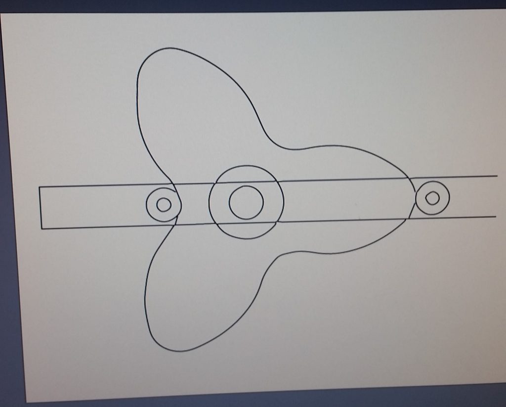
As is clearly visible, this didn’t come out with any level of perfection, despite my best efforts. For this reason, I decided to use a combination of image trace and reconstruction to construct my pieces as well as possible. I began by getting the straightforward ones out of the way, drafting all of my circles with appropriate centers and diameters, and also completed the rectangular shaft.
SIDE NOTE: whenever I began construction new shapes, I did so in different layers. In this way I can hide and unhide different layers depending on whether I want to either show someone the entire reconstruction, or perhaps isolate one item in preparation for laser cutting. Either way, I am ready with a few mouse clicks.
Having completed the ‘easy’ steps, I then turned my attention to the gear component. With any hope of getting a laser cut version to actually function, the curves would have to be exceedingly exact, and my initial tracing was not even a complete curve at this point. I began by completing the shape with the pen tool, then modifying its curvature in points of interest using the curvature tool (which is very handy, I must say.) This resulted in a somewhat better looking sketch, seen below: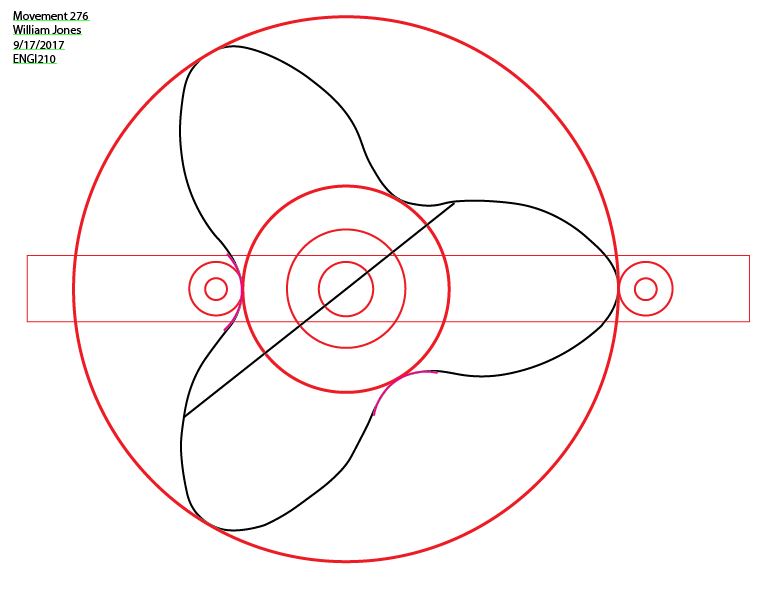
In this drawing, I have made my “test” layer visible, which I have done in order to show you the lengths I went through to ensure that my gear was as symmetric as possible. I have an inner and outer circle, ensuring that my min/max extents of each tooth match the others, and are tangent to these test circles. In addition, I drew circular curves to try to fit the grooves as accurately as possible, moving curve points with the curvature tool. Last but not least, I drew chords at random locations (one shown above) trying to ensure that the diameter of the gear was identical at all points. Sadly, I found that in some areas I had deviations as much as .2″ (out of about 5) and so I decided to try a new approach.
New Approach and drawing finalization
My wonderful plan to ensure symmetry was to cut the shape I had already created at the 3 minimums, take the most ideal looking ‘leaf,’ then duplicate it twice and construct my own gear. From the previous image, you can see that my upper left gear appears the most ideal, and so I cut it out, pasted it twice, and finalized my own ‘perfect’ gear, shown below. This required extensive further use of the pen and curvature tools, as I had to connect the three shapes, then remedy the incorrect curvature that resulted at the connection points until I was satisfied with the shape.
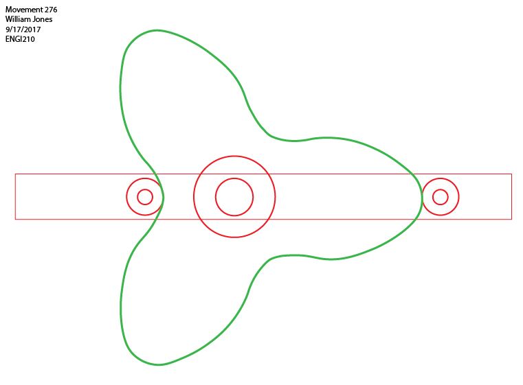
With this implemented, all my test shapes remain satisfied, and the gear is certainly more precise that in was before.
conclusion
In conclusion, I would say that I have learned a huge amount from this homework assignment. Even though I sank more hours than you would expect into it (I began with absolutely never having even heard of illustrator) I did not mind them at all, and I have even begun using the program to construct drawing of things of interest to myself. In addition, I was able to learn much more about specific tools within illustrator, particularly the image trace/ live trace functions and the curvature tool. I look forward to drawing many more objects in the coming weeks, and I hope to be able to physically construct some of these mechanical motions as well!
Last but not least, here is my AI file. Feel free to hide and unhide whatever layers you want to visualize my process and progress!
Mechanical Movement – Curves Smoothed
