While I was choosing the mechanisms to draw this immediately caught my eye, as I know where exactly I’ve seen it before and how it’s applied in real life: a car jack!
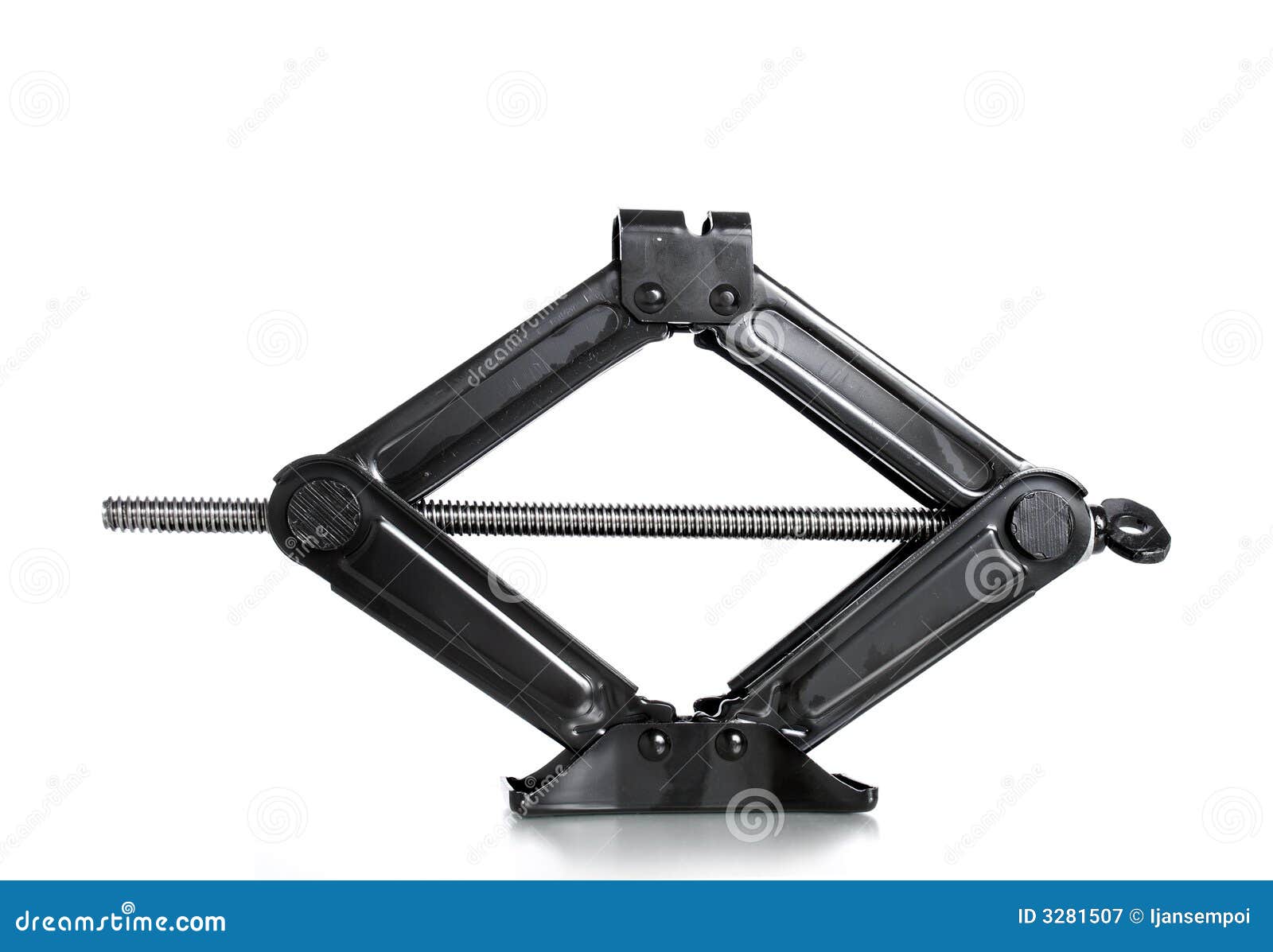
You don’t forget this very easily if you’ve used it, especially when it has saved your life at 3am stranded on a freeway.
The mechanism itself is called a rectilinear to rectilinear motion, to see how it works, you can view this gif from the 506 Mechanical Movements website, or watch how this instructional video on how to jack up a car safely.
I decided the image wasn’t too complicated that I could simply put it as a base layer and draw it from scratch with multiple layers on top. I wanted to make sure that I segregate the layers according to the different components, which turns out to be a little complicated sometimes when AI has a mind of its own and jumps back and forth between layers without you knowing.
Anyway my first layer began with the circles, and this is a close up shot of how it looked like.
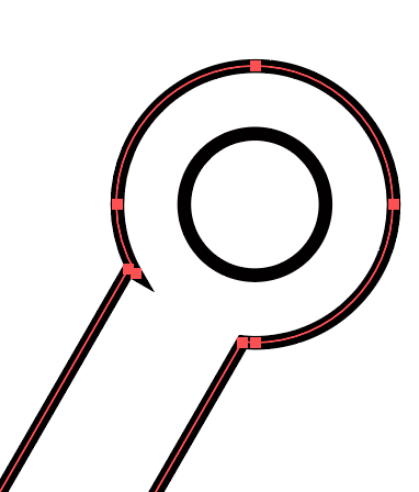
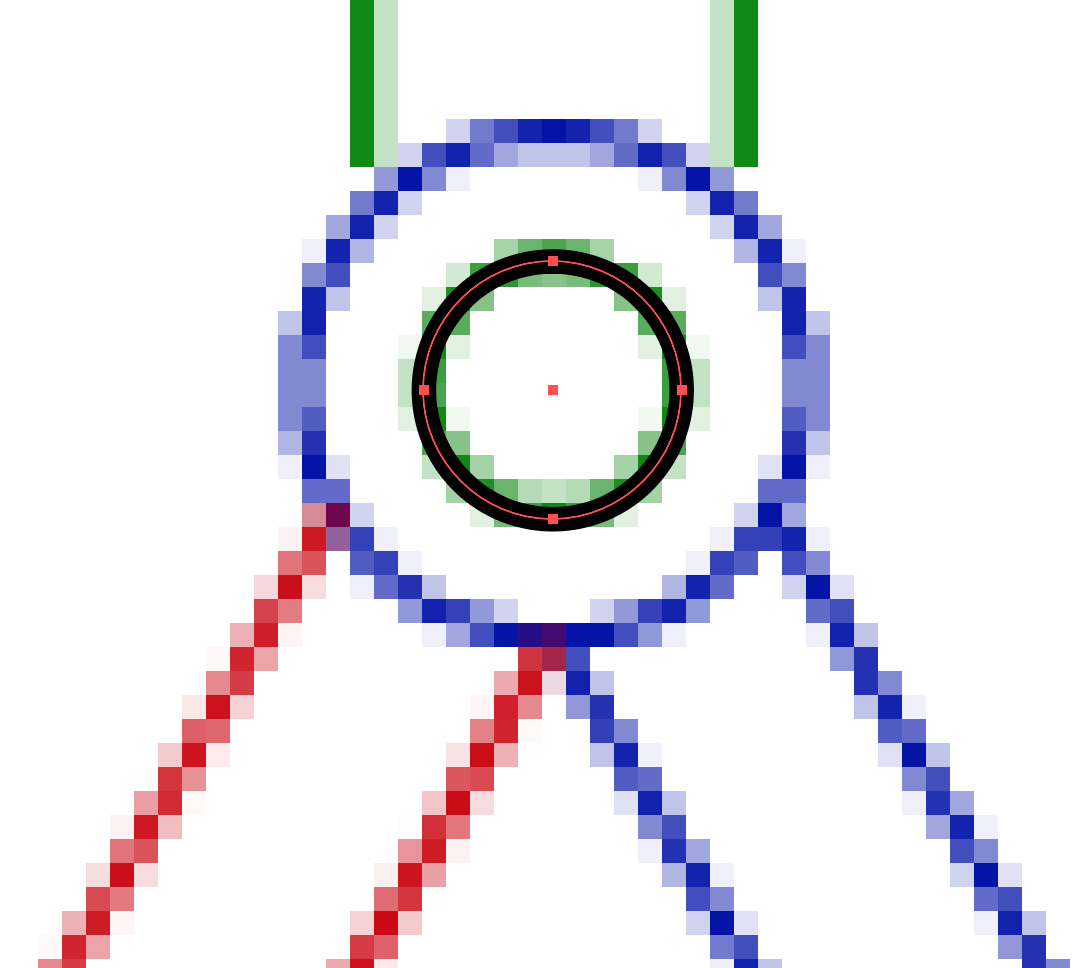 I then drew the outer circle, and drew lines to represent the rods. To make sure that I lined that up properly, I would intersect the lines and the circles at where the anchor point was (see below).
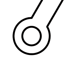
 After I’d done drawing the lines I stared at the mechanism and something felt wrong to me. This was supposed to be a rod with two holes, something that looks like a wrench:
 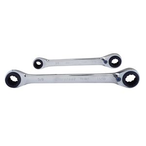 I tried using the cutting tool to remove the excess lines, but encountered this problem instead:
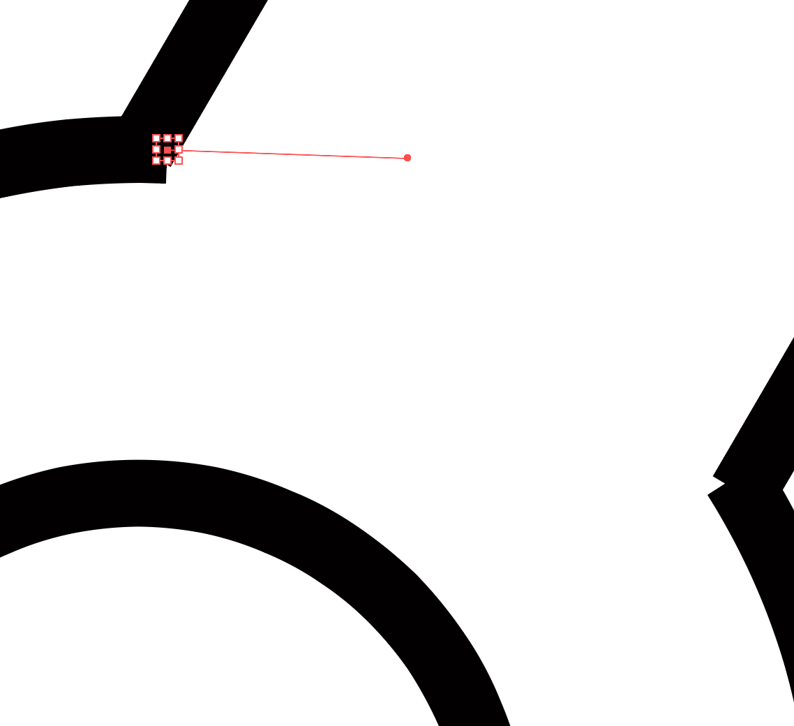 You can see that the lines were cut off at an angle, looking as if they weren’t joined properly. I’d tried using the scissors to cut at exactly where the anchor point was, but encountered a problem saying that I’m not allowed to select the anchor point. It looked okay from the afar, but it was uncomfortably inaccurate up close.
Another method of cutting didn’t look too good either. It looked like I was running out of luck with this incredibly difficult to use tool:
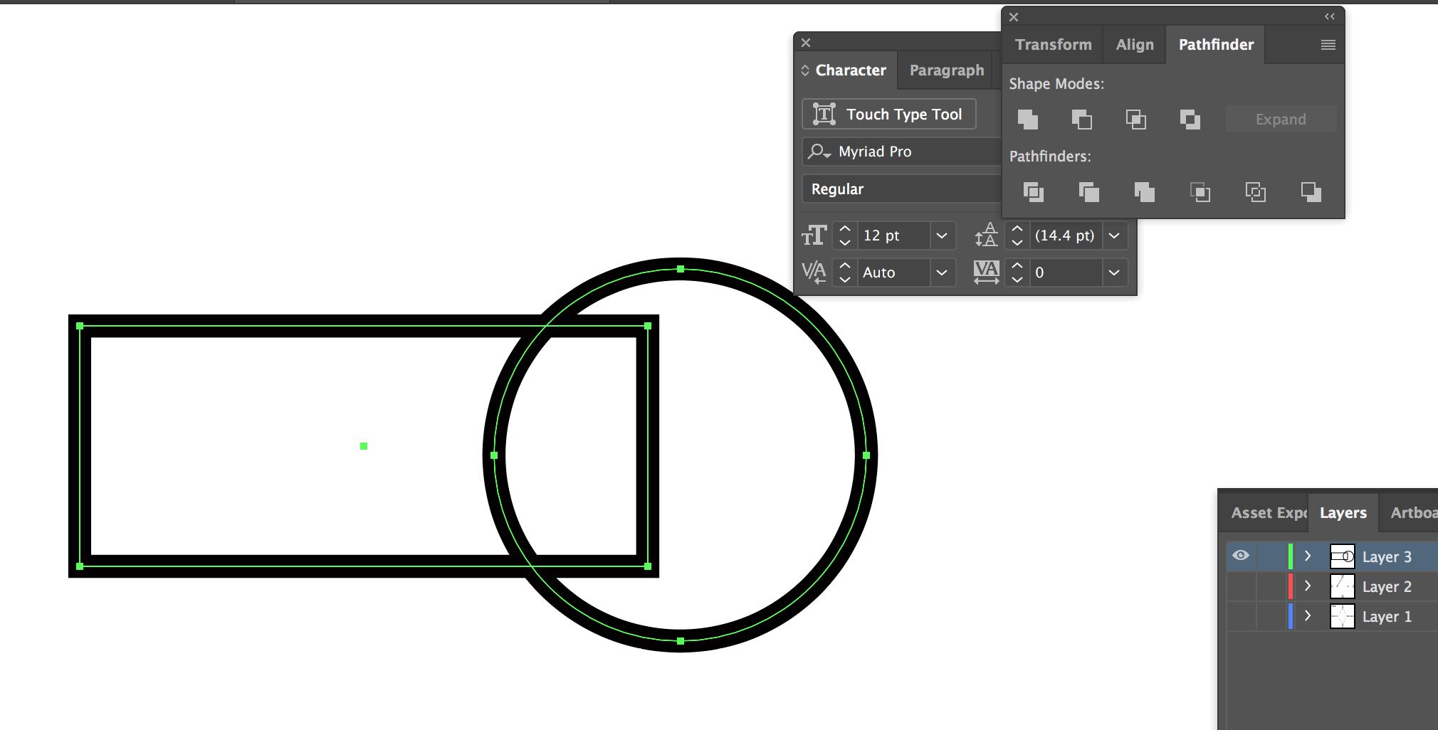
 I then remembered one of the techniques we’d learnt in class, which was to use the pathfinder and select the various merging tools. I erased my two lines and drew a rectangle instead. I then selected both the rectangle and the circle and used the pathfinder tool. Unfortunately, my first attempts at the “unite” tool to create a compound shape didn’t work. I would select both shapes and one of them would end up disappearing. I got frustrated and decided to open up a new layer and run some tests:
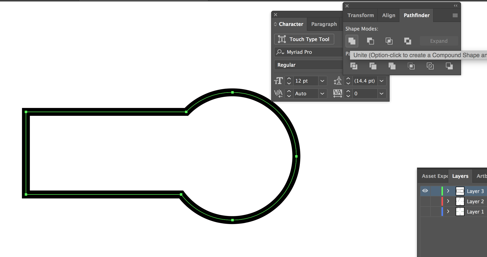
Magically these tests worked instead! I then guessed that my circles and rectangles weren’t overlapping a large enough area, or the outlines were too close for AI to be able to detect my shapes properly, and decided to lengthen my rectangle to increase the overlapping area. I gave the “unite” tool a go again, and it worked!
The rest of the parts weren’t too complicated afterwards. I simply copy pasted and rotated the rods for the four rods in the middle. The fixed rectangles were drawn on a separate layer, and the control rods were drawn on a separate layer. 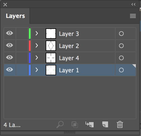 I made sure to arrange the rods like how they would in real life, with one on top of another until the fourth rod, and these controlled rods (the ones that looked like wrenches) were seen as “above” the control rods from the side view. In reality, such as the car jack, the control rods can be understood to be in between the “controlled rods”, which makes sense when you view this diagram from either side.
 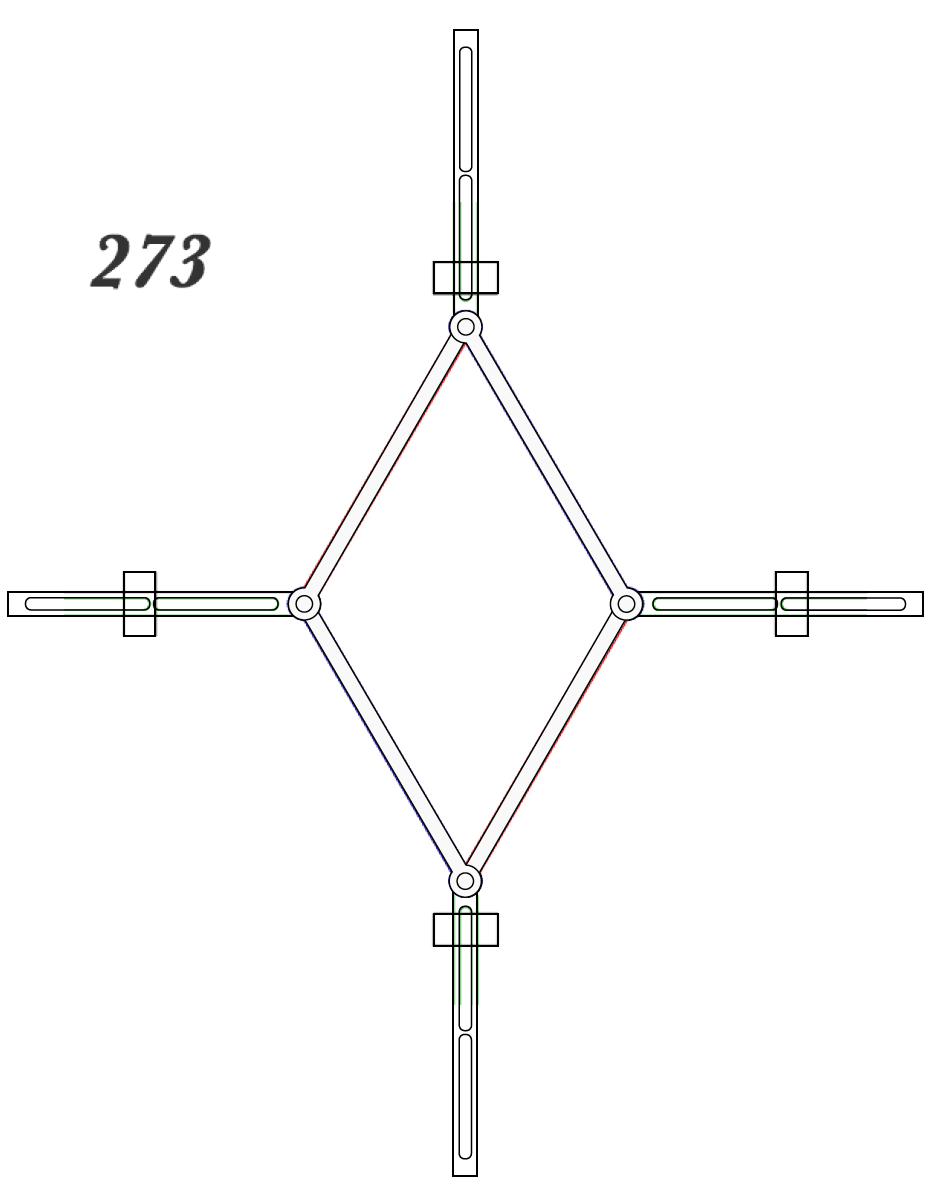 The AI file can be found here.
