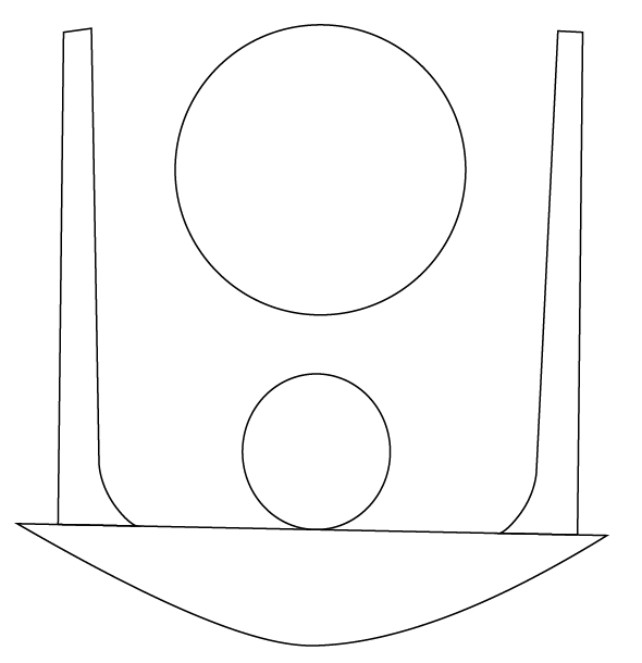
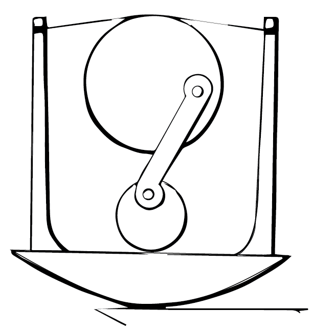
1. Choosing a movement
The first step was choosing a motion to replicate. I wanted to look for some kind of reciprocating mechanism, as this might be useful for my senior design project. Based off the index, number 419 seemed interesting and complex. An animated version can be found here.
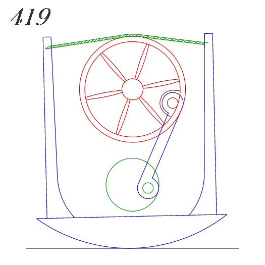
Animated depiction of rocker, mechanical movement 419
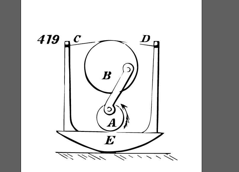
2. Importing file to adobe illustrator
The next step was to simply copy and paste the image into Adobe Illustrator, to begin working with it. I decided to use the drawing instead of the animation for this, since it more accurately depicts the original design. This was likely hand-drawn, so there are some slight differences from a computer generated version and this file.

Importing picture into Adobe Illustrator
3. Image tracing
To convert this into a drawing, I first tried to use Image Trace, which automatically creates vectored graphics from the imported image. The tracing result is shown below. Some areas, especially thin lines, do not appear on the traced image, due to it not being registered as an area to fill.
Vectored image
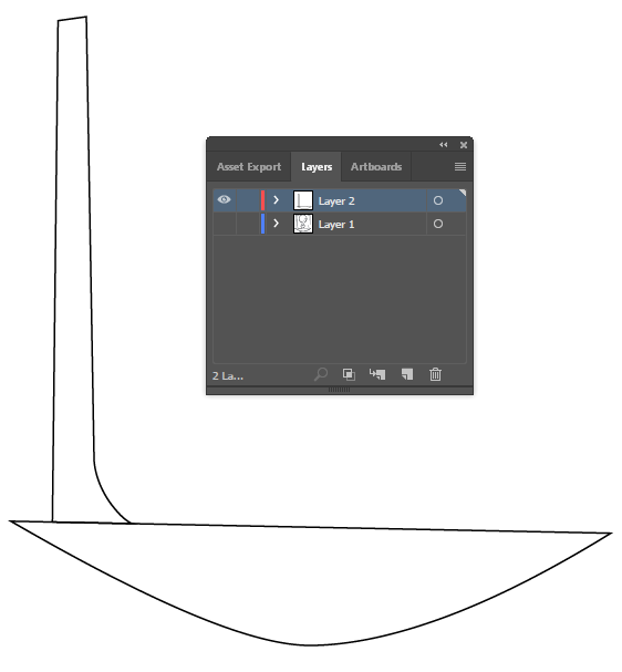
4. Removing the fluff
The next step was to delete all superfluous items – the letters, arrow, floor, and number. This is to isolate the mechanism itself. Some areas could not be easily removed, like the floor, because it is directly attached to the rocker, so those parts remained for right now.

Isolated mechanism
5. Use layers to trace the image
Due to the poor result of image tracing, with overlapping lines and missed sections, I decided to trace this manually instead on a separate layer. Using the pen tool, I traced the base of the rocker and the left post. I used the direct select tool to drag the points and handles to accurately line up with the imported image. I then hid the image layer to only reveal the drawing.
Part of traced image, with layers shown
6. Flipping and transforming
I wanted to duplicate the post on the left side on the right side, since I assumed they would be symmetrical. I created a duplicate with copy and paste, and then reflected the post vertically. However, I noticed that the right post was at a slightly different angle than the left, which meant that when I duplicated it, the new post didn’t align perfectly. I used the direct select tool to drag anchors around to more accurately match up with the original drawing.
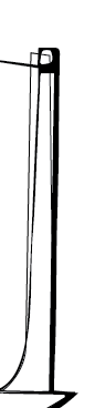
Misaligned lines and drawing, before manually fixing
7. adding the circles
This step was pretty simple. I just used the ellipse tool and held shift, and resized/moved the circles until they properly matched the drawing.
Both posts, circles, and the rocker
8. Adding the arm
First, I drew the exterior circular parts of the connection arm with circles, and deleted the extra parts with the scissor tool. I then added lines from the anchor points, and adjusted until they matched the drawing. I used the pen tool to connect parts of the exterior circles to the lines. The interior circles were just simple circles placed in the proper location. I joined the path of the circle arcs and lines by highlighting the desired paths, and then going to Object -> Path -> Join (Ctrl+J). This converted it to a single object, which I then filled with white. The other circles are added with the pathfinder tool. I selected the three shapes, and then used “Minus Front” pathfinder mode to remove the two top circles from the arm, so we now have one single shape.
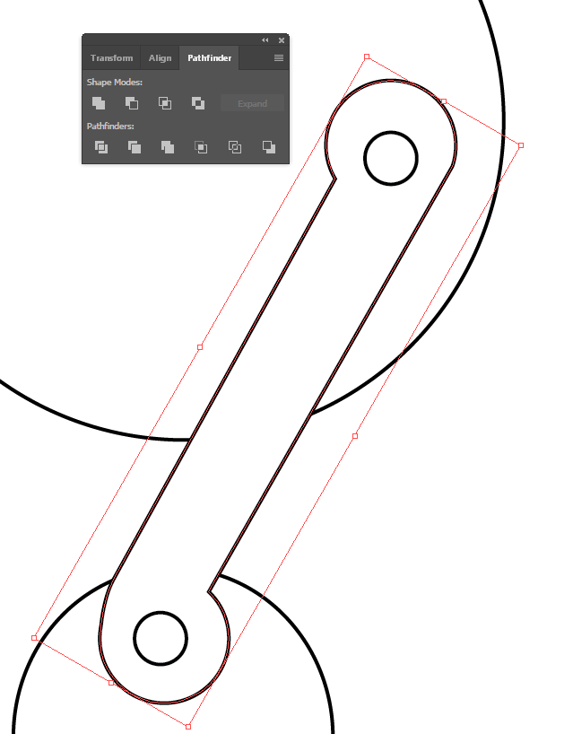
Arm with pathfinder window
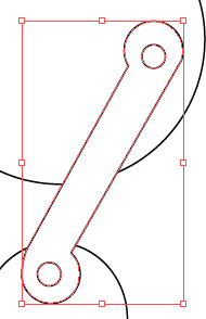
Result after “Minus Front”
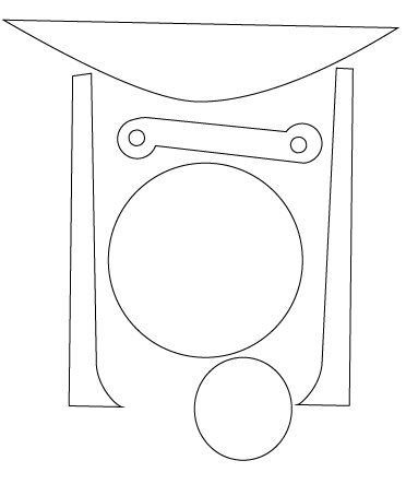
9. Adding the rope
This was another step that used the pen tool – I drew a close approximation of the rope contour, and the adjusted until it properly matched with the direct select tool. I used “Anchor Point Tool” to add handles to the end points. This essentially completes our drawing! (While the rope is not a part that needs to be fabricated, I decided to include it here, as it would be confusing to figure out how the mechanism worked otherwise. In the laser cut preparation file, it is not included.)
Final drawing, with rope
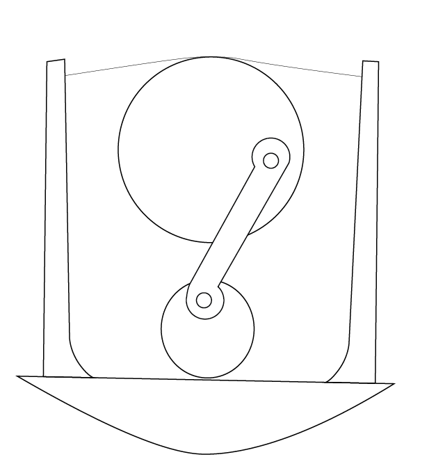
10. Finishing touches
I kept turning on and off the image layer to see any discrepancies, and this was the final result – the traced version is difficult to discern due to overlapping with the image. This let me know that my drawing closely resembled the original mechanism.
Drawing overlay with image
I then colored the drawing to more clearly show the layers, and make it look prettier.
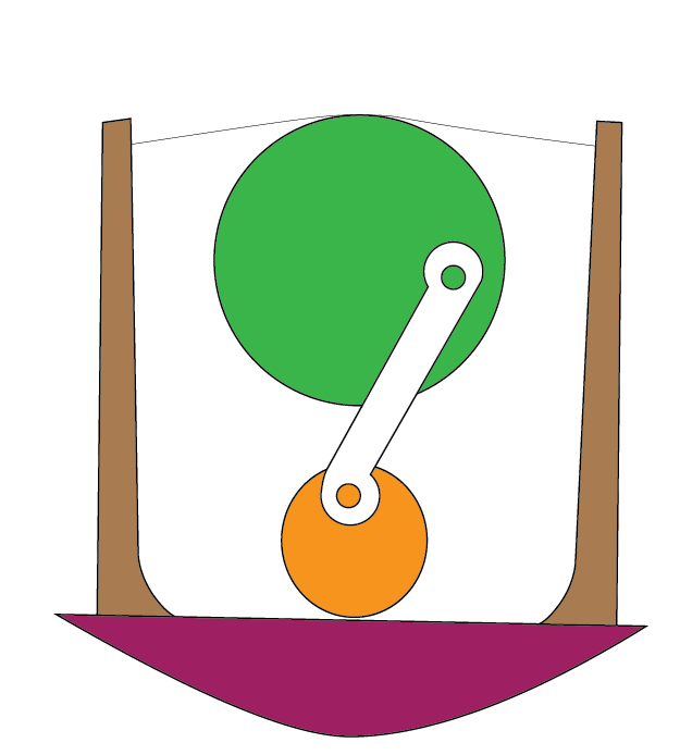
Colored image to show layers
11. Preparation for laser cutting
If we desire to make this part from laser cutting, we should properly organize the pieces to minimize the wood used. We also do not need any rope, since that is not something we would produce using the laser cutter. The parts have been arranged as follows:
Laser cut ready!
