0. Motivation
The design was chosen to be Mechanical Movement 419, found here. I found this to bean interesting mechanism that had a decent amount of moving parts, so I was hoping to challenge myself with the complexity of the design.
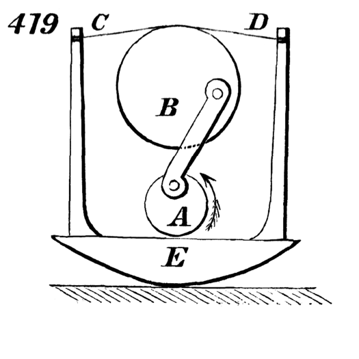
Original Mechanical Movement
1. 2d drawing
The following is the final result from my 2D drawing, made in Adobe Illustrator. The pieces were split up into 3 different artboards to help categorize – the rocker, the internal movement, and the framing. One thing I realized initially is that if I made the holes too small to try and get a press fit, the wood would start to snap. The basic design did not change too much from each iteration – hole placement and size were the biggest changes – other changes will be talked about throughout the post.

2D drawing
2. First Rocker
The first step I made was the initial rocker. This was a medium fidelity prototype – so rubber bands were used as the connection between the posts. The holes were too big to fit the vertical supports snugly, so when the rubber bands were applied with tension, it pulled them close together. Furthermore, my glue job was not done very well, because I used way too much. I learned in future iterations to use less glue, and to wipe off the excess, so I am not left with the yellow staining shown below. I also made note to add cross beams for more support in future designs.

Initial Rocker

Bad glue job
3. Framing
The framing consisted of 4 pieces – a base plate, two vertical supports, and a top support. I messed up my finger joint the first time with the top support (they were not offset), but overall this step was not too difficult. I engraved my name and the movement on the bottom. I also had the make multiple iterations of the vertical support, to get the holes lined up properly for the rotational mechanism.

Messed up top support
4. Final Rocker
The final rocker design did not change too much from the initial design, as it worked well for my design. The rubber bands were swapped with a higher fidelity material, and the hole sizes were fixed. I had made the holes slightly smaller than the thickness of the wood, and sanded it down to get a snug fit, before applying a small amount of glue. Cross beams were added between the curved pieces for support, and the curved pieces were stained with Gel Stain for accentuation. The material used to replace the rubber bands went through a couple iterations – first string, which began to fray, followed by a stronger, more elastic, and less prone to fraying tubing. I spent a while trying to tie this properly, as slippage would mean the integrity of the piece would start to fail. I wrapped the tubing around the dowel, and then tied a knot. The knot was eventually fixed with Super Glue.

Dowels used as cross beams

Gel Stain that was applied

Initial string used – would fray easily

Final tubing used – plastic, so no fraying, and slightly elastic. Knot with excess cut off

Close up on hole joints and staining
5. Plasma cutting and post processing
The next step was plasma cutting. I had decided to use the linkage between the two rotating mechanisms, as this was a functional piece, and could be accented in a neat way. I realized that with the inaccuracy of the plasma cutter, my internal dowel holes were too small, and not very clean. They were fixed up with a drill, to make it slightly wider and smoother. The steps used were angle grinding -> sandblasting -> drilling -> spray painting.

Initial plasma cut

Final piece, finished and spray painted black, in the rotating mechanism
6. Rotating mechanism
This part consists of 3 pieces – the plasma cut piece previously made, and two circles of different diameters, the smaller (lower) one which rotates continuously, and the larger (upper) one which rocks back and forth, causing the movement of the rocker. The plasma cut linkage moves around in a circle on the lower piece, which pulls and pushes on the upper piece, to create the movement. Small wooden retainers were used to constrain the design axially, which I initially did not think needed to be done, until pieces started to slide off. The upper circle went through a couple iterations, to achieve the proper diameter for the rocker. The lower circle has to be cantilevered, to allow for the linkage to rotate 360 degrees. Support for this is addressed in the next step.
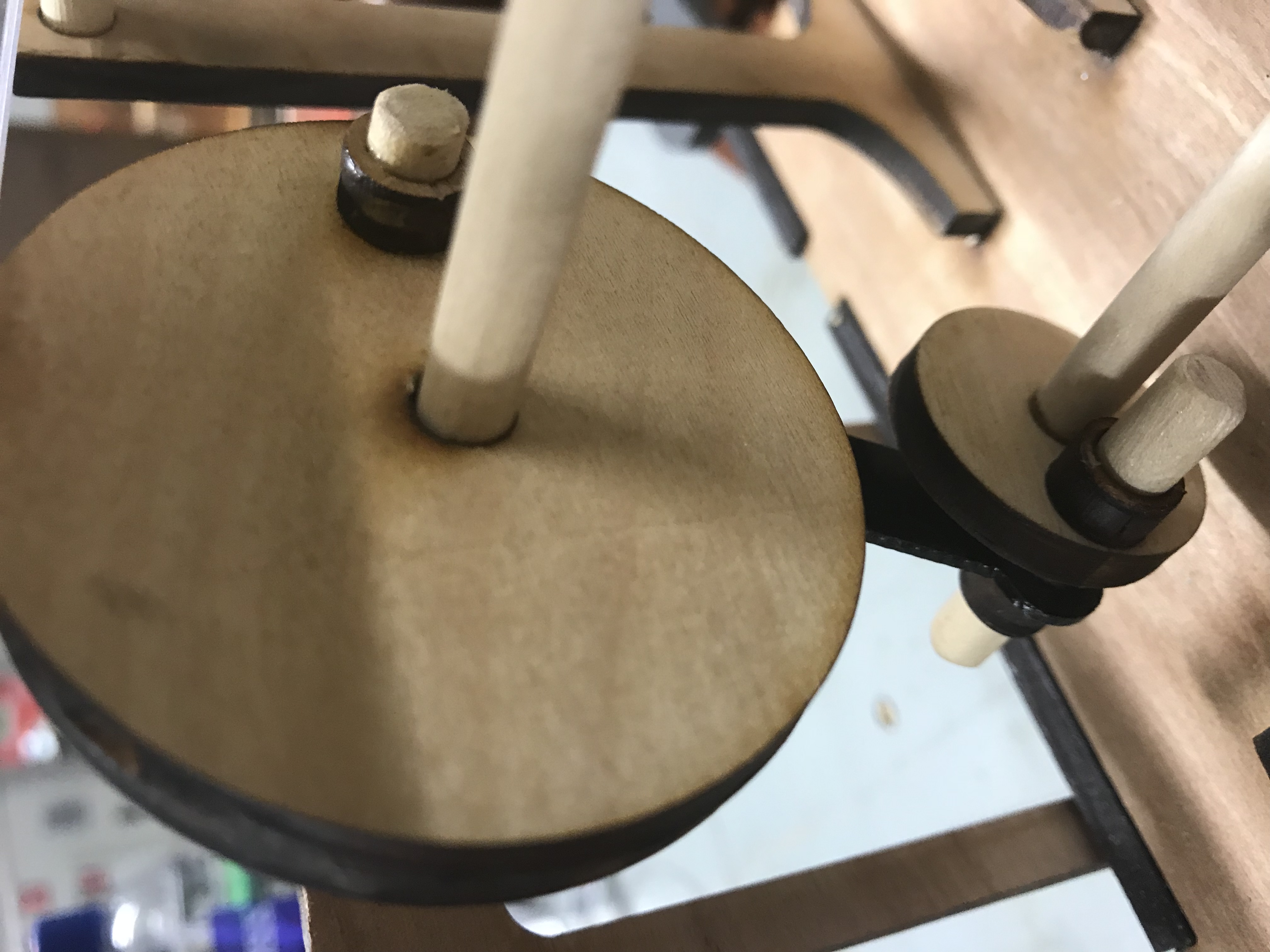
Rotating mechanism

Upper circle

Retainers
Rocker from back – note cantilevered lower circle, to allow for full rotation of the linkage
7. Finishing touches
Lastly, the plastic tubing was fixed to the upper circle. First, super glue was used, until it failed. Tape was successful, but did not look good. I finally decided on a higher strength epoxy, which seemed to have gotten the job done.

Attachment with epoxy
Additionally, the handle was attached, and support was added for the lower circle, since it was a cantilevered beam.

Handle with arrow for guidance

Support for cantilevered beam – one retainer used for support, the other used to constrain axially on each side
8. Final Design

Isometric View
Note the different positions of the rocker, based on the input

Position 1

Position 2

Back view
9. Lessons learned/Conclusions
Overall, I learned a lot in this midterm – tolerances with laser cutting, constraining things axially, precision of plasma cutting, and overall how to design in 2D to create a 3D object. While this was a challenge and quite time consuming, I’m quite happy with how it turned out.
