What up fam. This post is coming at y’all live from the great town of Dripping Springs where there are actually no “dripping springs”. Anyway, over the past week and a half we were tasked with designing and laser-cutting a divider box for all of the projects that we will have this semester. Seems pretty simple at first but the more you work on it, the more complicated it gets.
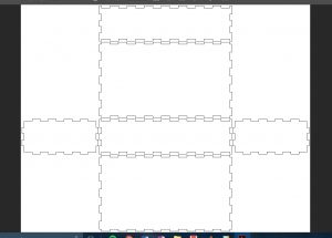
To start out, (since I had never made a box before) I used makabox.io to just get a feel for what the finger joints would look like. After throwing in my dimensions for the outer box (12.5 x 7 x 3) this is what it gave me:
After looking at the dimensions, I found that the pegs were larger than the spaces they were supposed to fit into. This is due to the “kerf” or the amount of material that the laser burns away due to its own thickness. From here on out I knew that if I wanted this box to press fit together nicely, I would have to pay a lot of attention to the dimensions of these tabs and find the best amount of overlap to use for my box.
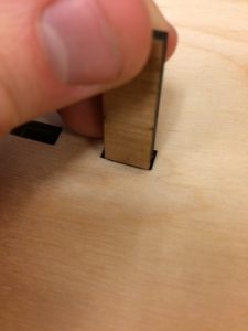
After trying to dimension and make additional dividers for the box in Adobe Illustrator, and realizing that Adobe is utter crap at dimensioning anything, I knew I’d have to go back to my old trusted friend, SolidWorks. But before I did that, I needed to know the ideal overlap for the wood we were using. I tested out a few different sized rectangular pegs in a half inch rectangular hole and found that an 0.02″ overlap (or 0.01″ on each side) overlap gave me the best press fit. It fit within the hole tightly and didn’t move easily at all. I forgot to take a picture of the actual pegs themselves so here’s and example of what the setup looked like:
 Once I had that, I started making the box! Yay! For the longer sides I decided a 1 inch tab would work fine, so I used a 0.99″ gap and a 1.01″ tab so that they would have the 0.02″ overlap like I discussed above. Once I was finished with the base, I moved on to the sides and followed the same pattern for tab sizes. For the sides to interlock with each other I used 0.49 and 0.51 tabs and gaps. Then with all of the sides made, I made an assembly out of them and had a damn good looking silver CAD box. This is where it gets interesting (If you’re a nerd who enjoys SolidWorks). To insert the dividers into the outline of the box, I started with the divider and created its own tabs, and then inserted it into the assembly. Once I had it in its position I could then edit the different parts within the assembly to have holes in them for the divider’s tabs to fit into. This saved me a TON of time. I was able to edit everything within the assembly instead of editing everything one part at a time…. Kill me…
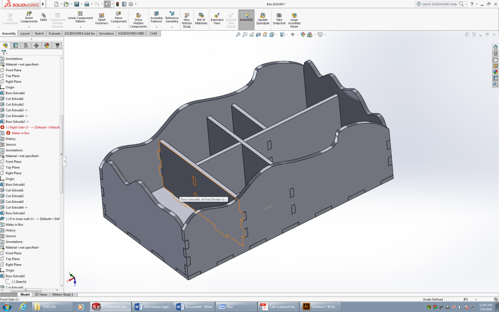
Here I’m editing the front side of the box
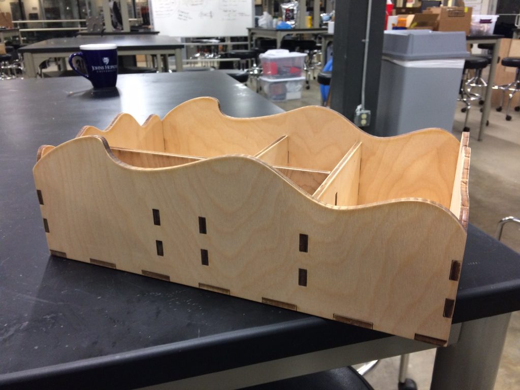
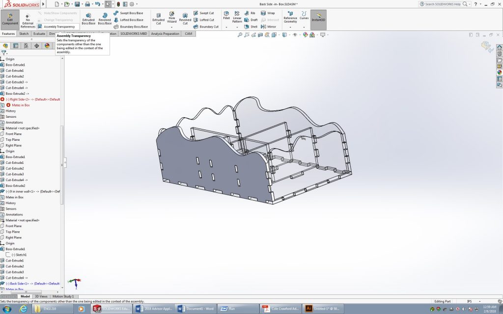
After figuring this out, I was able to crank our the rest of the inner dividers and add the holes to the existing sides pretty quickly. After that I wanted to have a little fun, especially because it was 12am at the OEDK and I was bored lol. So grabbed the spline tool and spiced up the top edges of my box by adding some dope curves. Behold, Curvy, the box making waves in the box community.
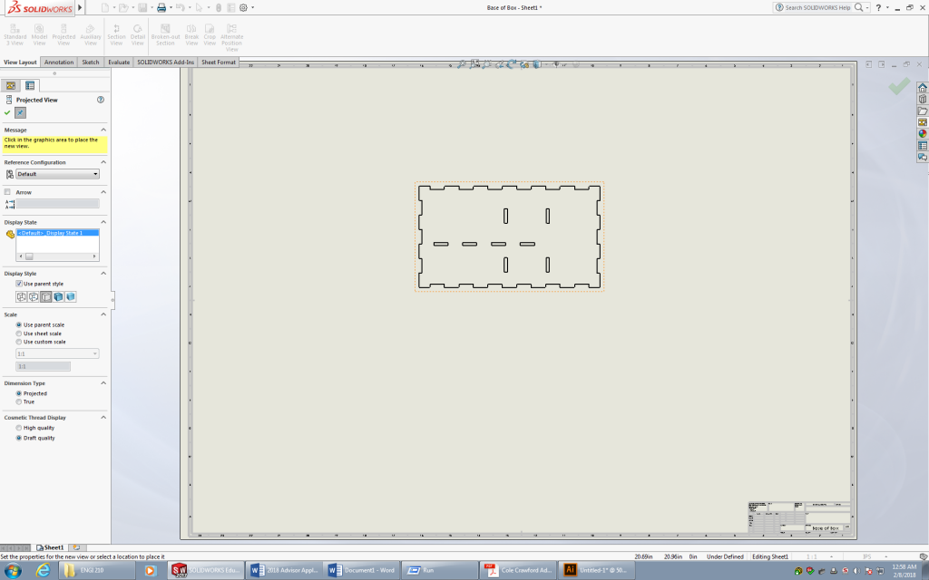
Now the last thing for me to do was to laser cut this bad boy. To export these files to the laser cutter, I had to create drawings from each part and then save that as an .ai file which I could then open in Adobe Illustrator. Here’s the drawing of the base of the box.
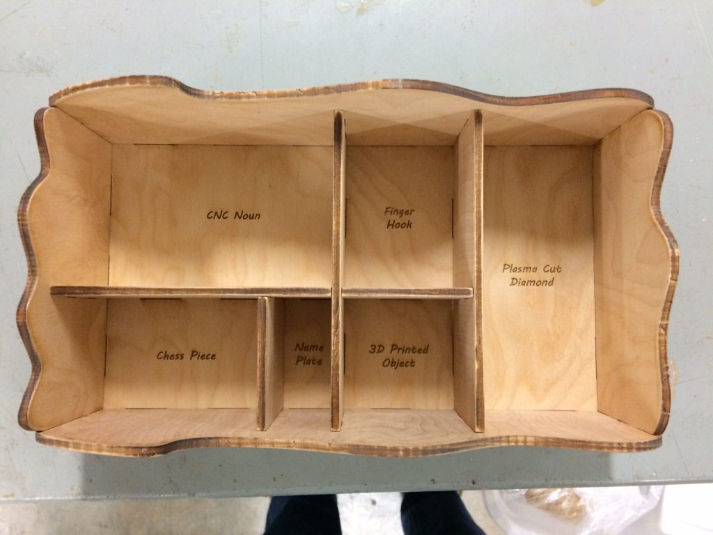
Finally, I laser-cut all of the pieces and prayed that they actually fit together. I did a test fit up and everything slotted into place PERFECTLY. You have no idea how happy this made me… I went ahead and cleaned everything up with some sandpaper and then put it together! These pieces fit together so tightly that I actually had to use a small rubber mallet to get everything to seat properly. Damn that felt good. Enjoy the box, and to continue the tradition: Live Long and Prosper Box.