Our final project was based on the Baroque Chess set located on Thingiverse.
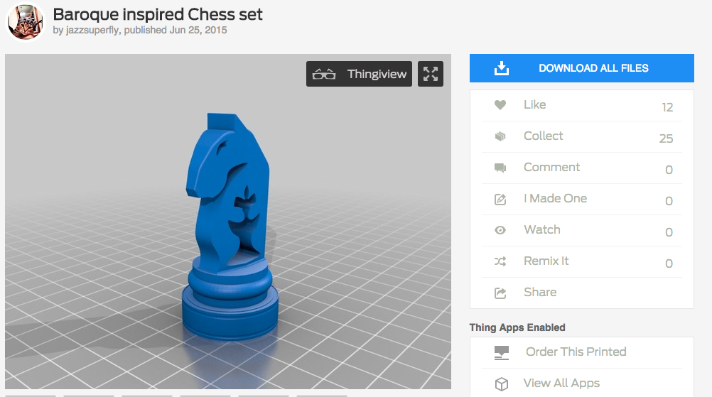
Baroque Knight
We chose this piece because “it looked dope” (Lester, 2018).
Our first step was to transfer the piece into Fusion 360. We followed the tutorial that Dr. Wettergreen provided, and sliced the part in half in MeshMixer. We then exported this half-piece into a file for Fusion 360. We then proceeded to struggle for 2 class periods to setup the piece in a way that it could be cut for a mold.
First, without modifying the piece (no pegs or air pipes), we attempted to setup a test cut for the Carvey. For this cut, we did an adaptive cut with a 1/8 in. ball end mill, with a 1mm roughing stepdown and .1mm fine stepdown.
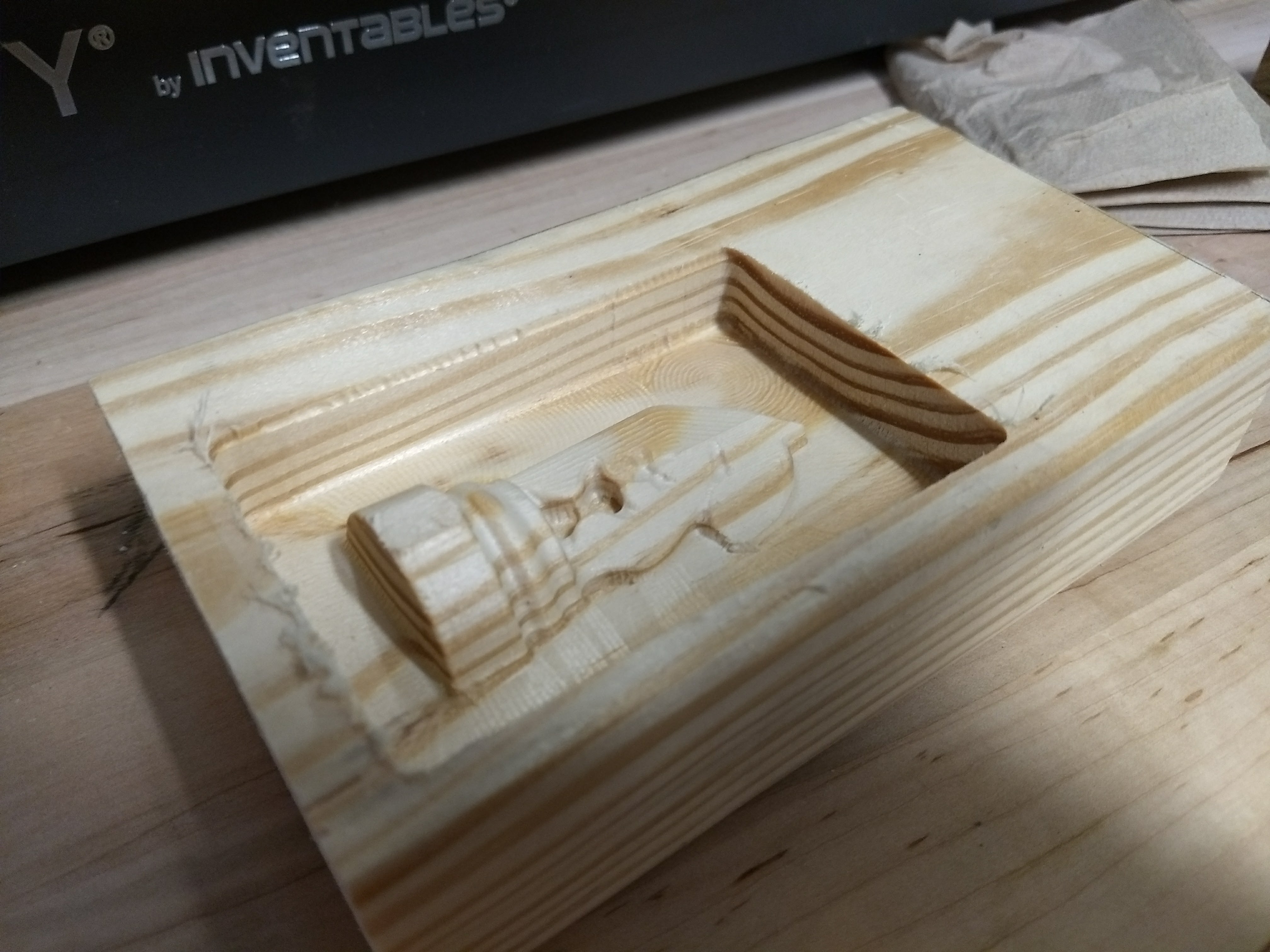
Test Cut
The cut succeeded, but we learned a few things. First off, the cut took >3 hours, and we found out that our step down was waaay too fine, and completely unnecessary. We also learned that we would have to be careful of where the piece was positioned on the wood, because the colored collar on the drill bit came awfully close to the clamp/collar/calibration thing on the Carvey.
Next, we added things to the CAD of the part. We included some register keys for the mold, as well as a tube for air to escape when pouring the piece.
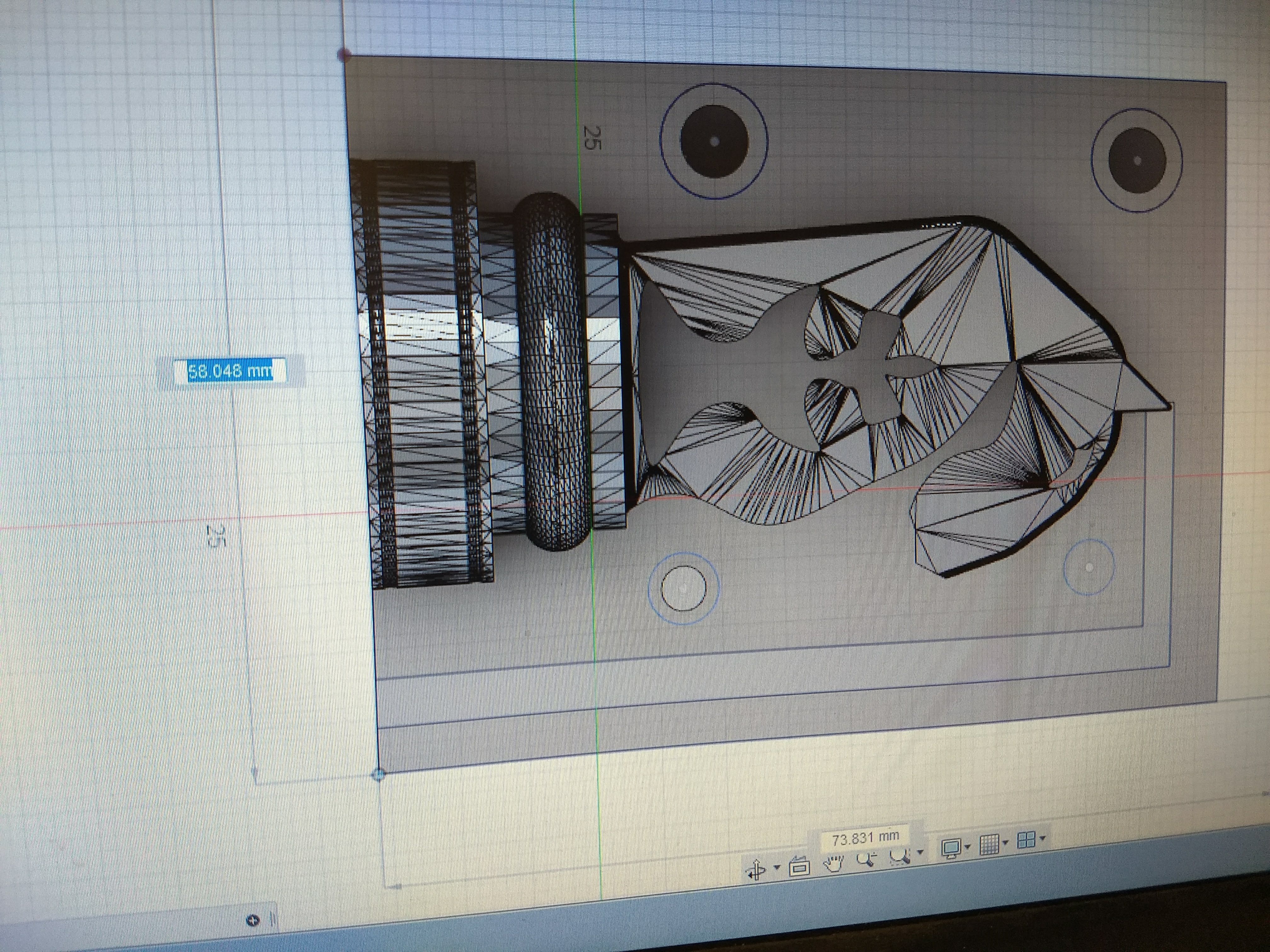
Final CAD Design
We also changed the step size of the rough cut to 2.5mm rough and 0.4mm fine. Additionally, we added a tool path for a fine cut, one that used a 1/16 in fishtail end mill. This cut would go along the contours of the piece in parallel lines spaced .3 mm apart to add fine details.
When we first attempted to cut our final design, we messed up. After cutting out most of the piece, the router head was too low, and the cut was positioned too close to the corner, so the router collided with the clamp.
Rip Clamp ( See silver marks on left side of photo)
After this mistake, we repositioned the part within the stock in the CAD. We also increased the bounds of the box so that the router wouldn’t hit the wood when the pinholes were milled.
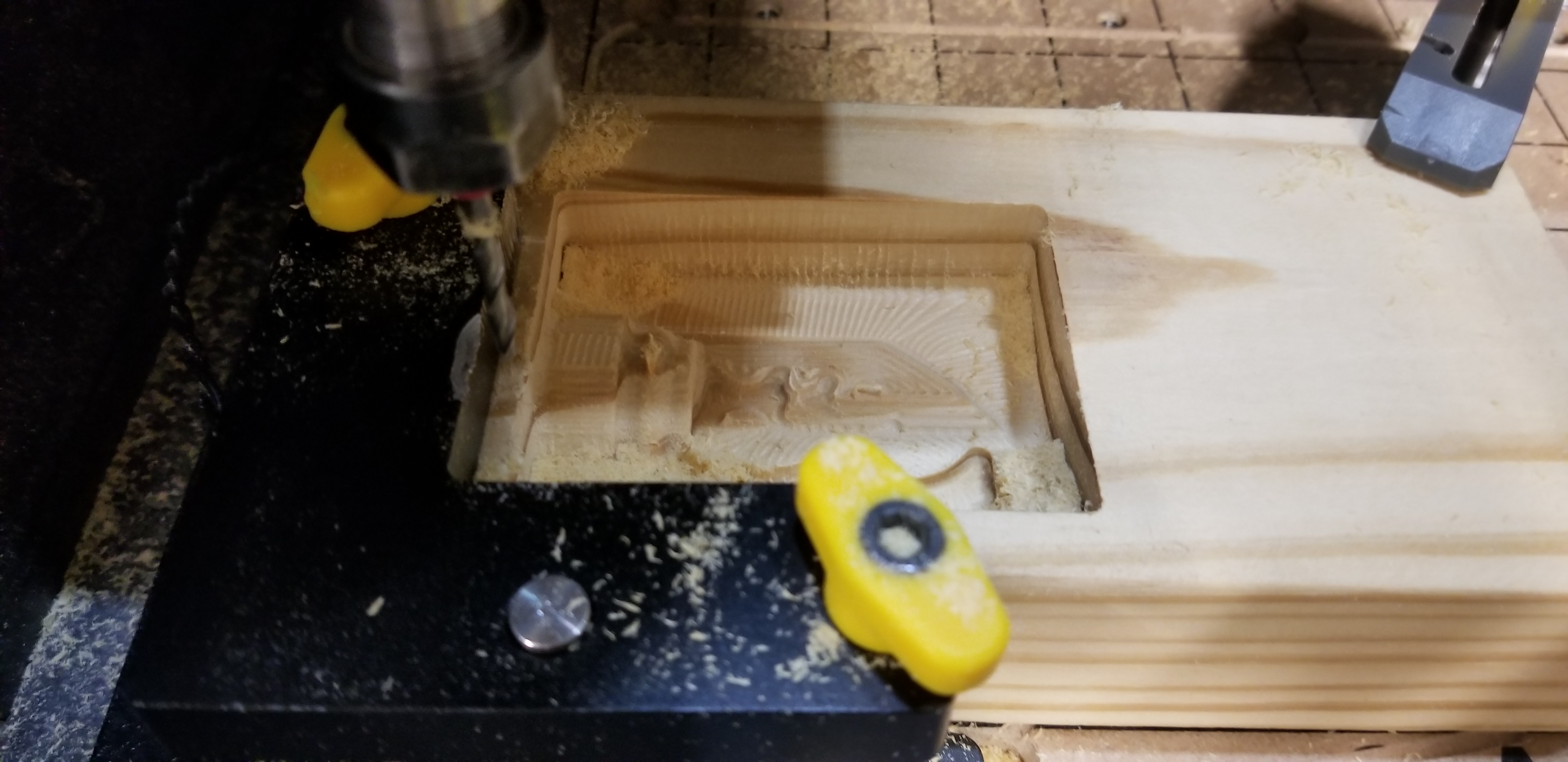
With these changes made, we ran the job on the Carvey again. This time the part came out great! The smoothing cut did its job wonderfully and the piece came out super smooth. During the smoothing cut, we had to lower the speed to around 50-60% whenever our 1/16 inch drill bit milled a section that the 1/8 drill bit hadn’t been able to mill during the rough cut. We also sped up the feed rate whenever we were milling over already cut surfaces. The rough cut took about 1 hour, and the smooth took about 2.5 hours.
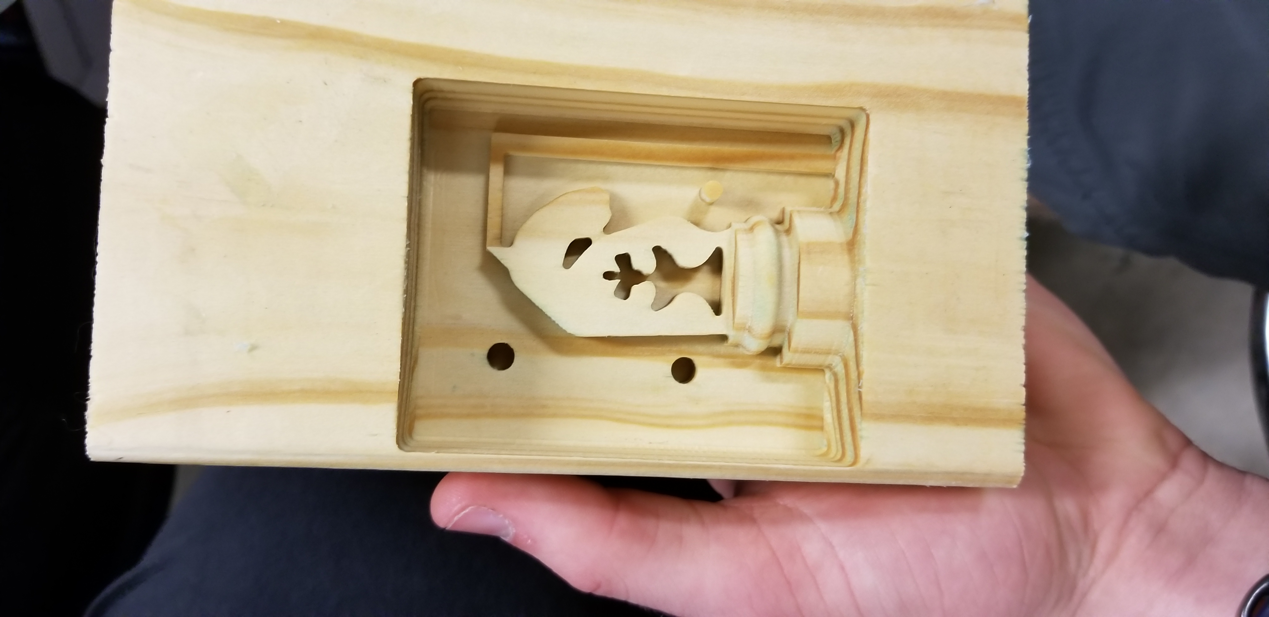
Our successful full cut for the first half.
*Note: We had some problems with the Carvey not resuming after being stopped midway through a cut, so we avoided stopping the Carvey as much as possible. This led to some comical amounts of sawdust buildup. This did not have a noticeable influence on the quality of the cut.
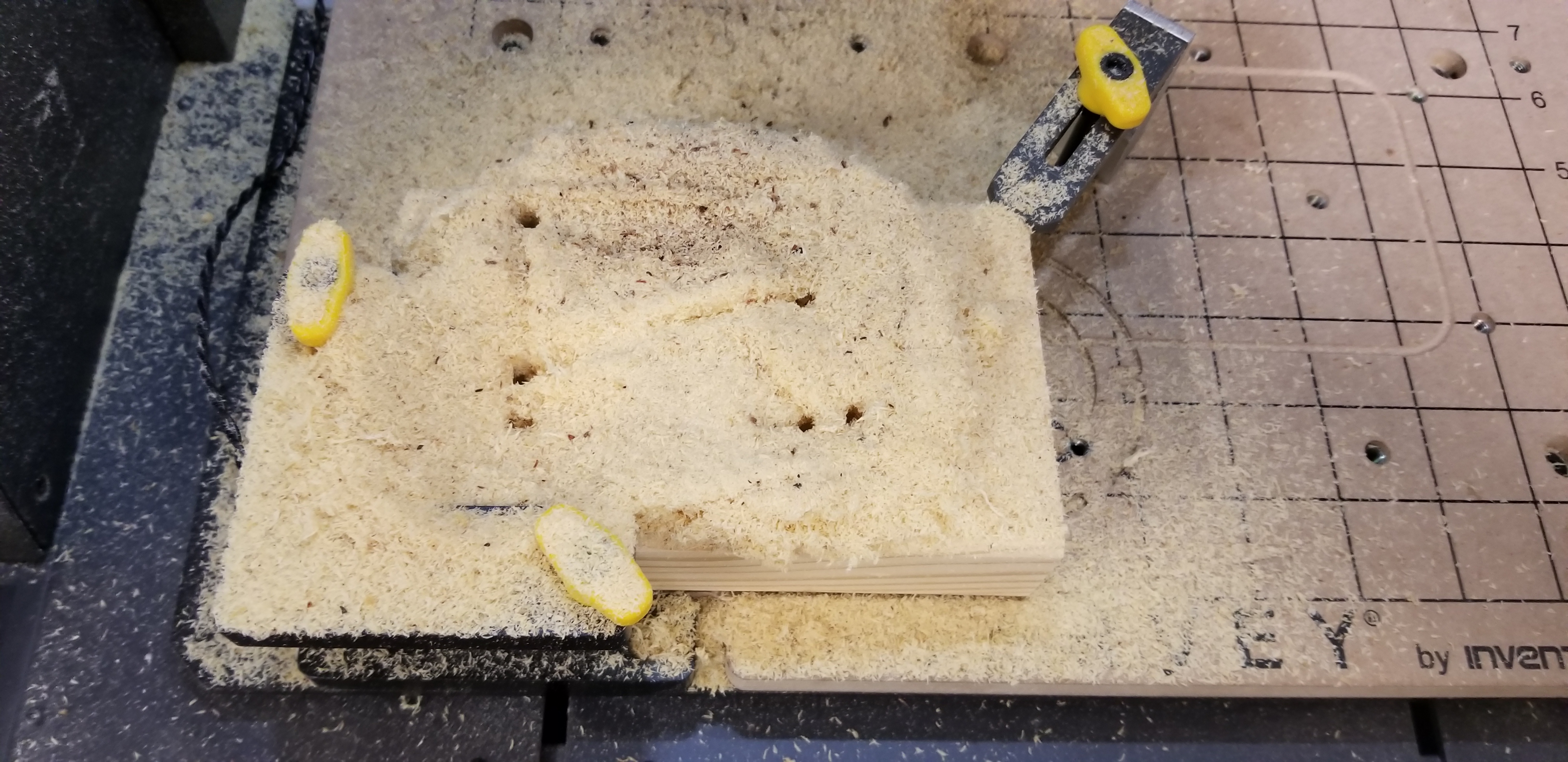
Comical Amount of Sawdust
Once we had the first half done, we created a mirror of the part, and inverted the peg geometries. To do this, we went back to Fusion 360, created a copy of the file, selected the entirety of the part’s body, and used the mirror tool. Then, we deleted the original side and adjusted the new mirror so that the pegs were extruded in opposite directions, and we adjusted the tool paths and stock box to the new part. After preparing the mirrored side, we began to cut it on the Carvey.
On our first cut of the mirrored part, we ran into two problems. First, there was a knot (or maybe rotten part) in the wood that we used, which produced a piece with various defects that would cause a bad mold (such as holes). Also, the bounding box that was set in Fusion 360 for our fine cut was too small, and didn’t extend to the entirety of the piece. This left an uneven bottom surface.
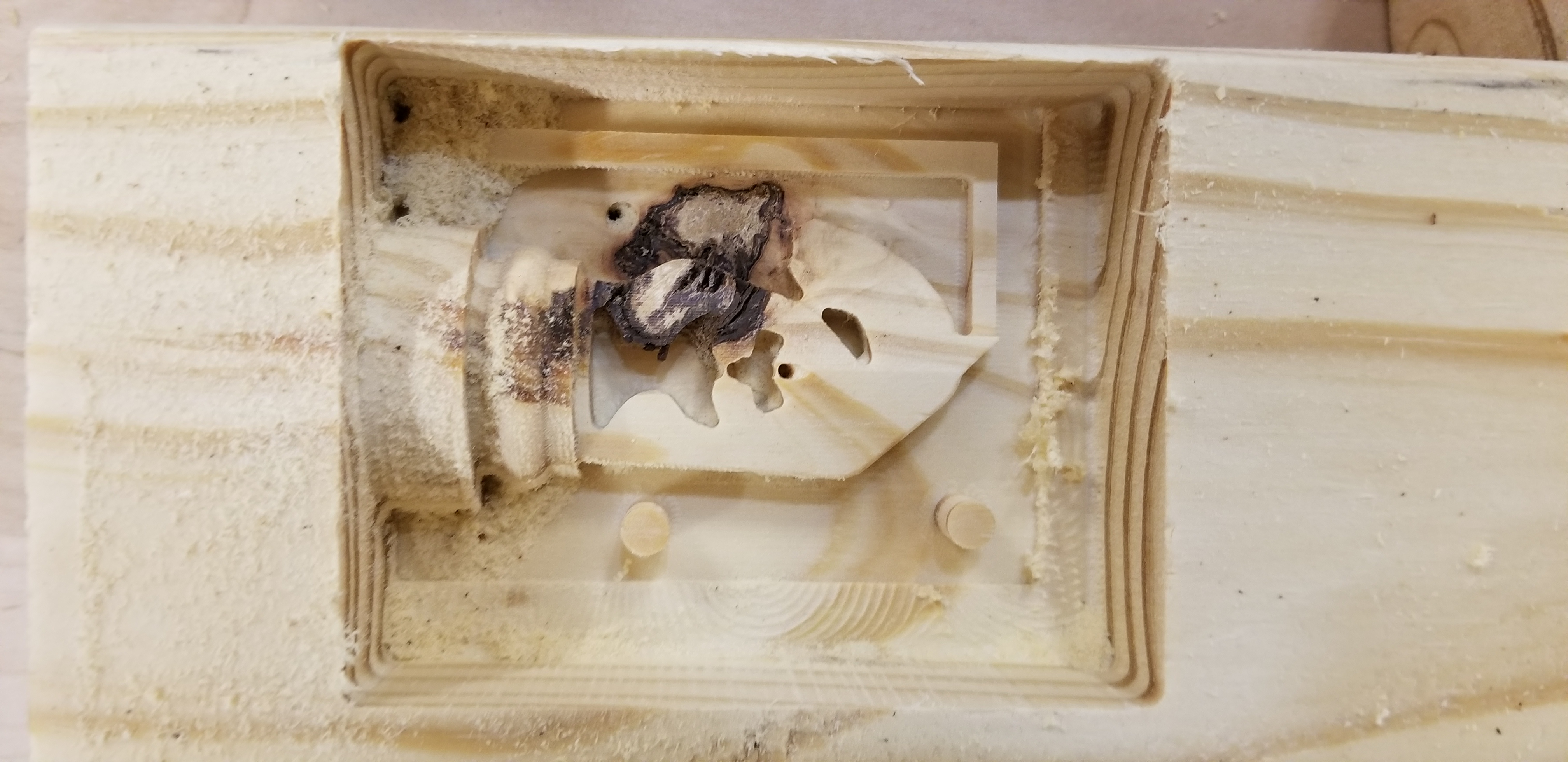
Rotten Wood and wrong box size for smooth cut
After this cut, we adjusted the box in the CAD, and recut the piece. This cut turned out great! Once again, this cut took a total of about 3.5-4 hours.
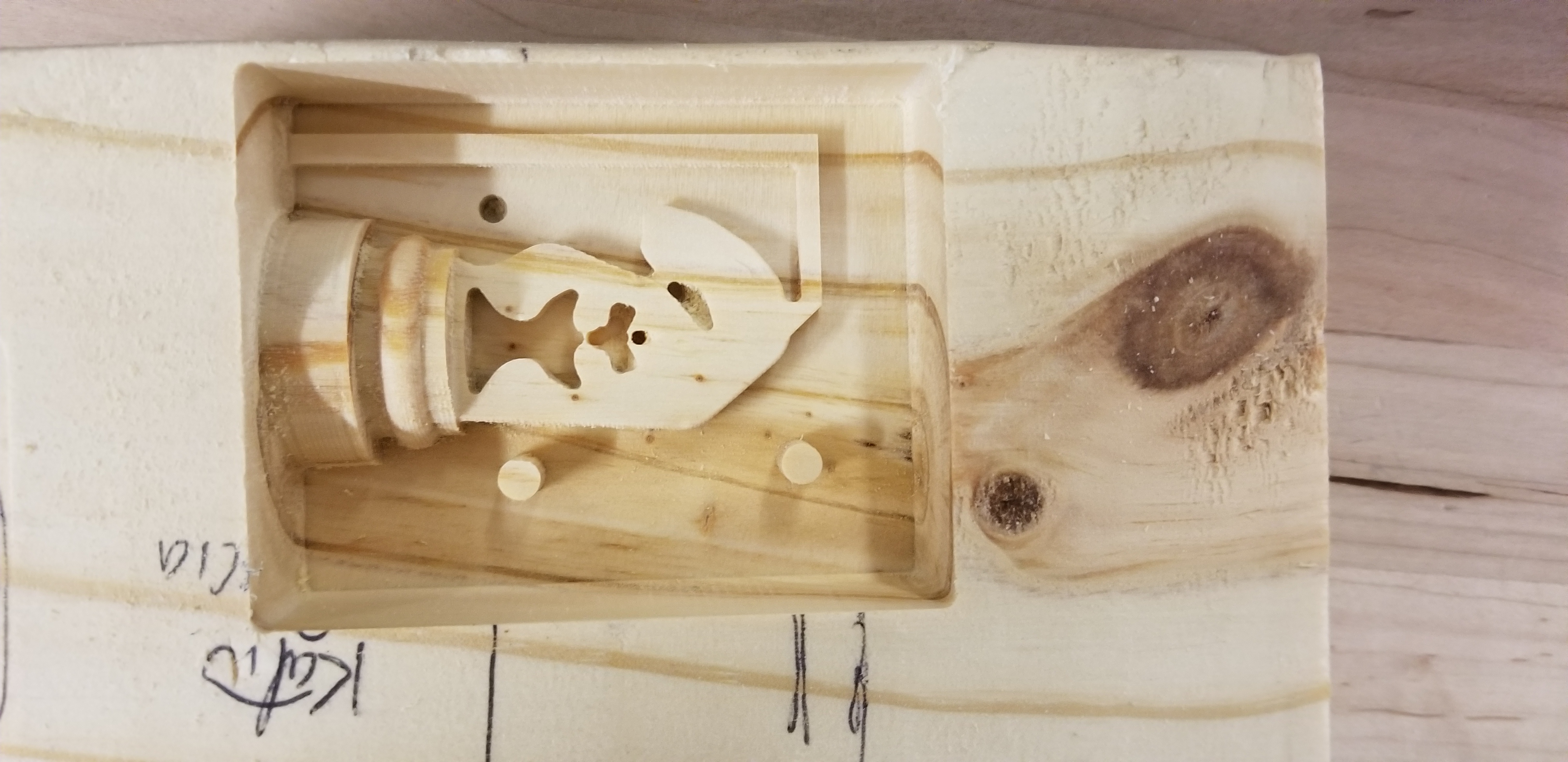
Successful mirrored cut
Now, we started to do our silicon molds!
When mixing the silicone, we used about 2.3 ounces of part A with 2.3 ounces of part B. To prepare the mold, we sprayed the mold with mold release, and poured the silicone mixture into it. After a couple of mold attempts, we found that the best mold was produced by pouring the mold and then placing the mold in the vacuum chamber for a few minutes to remove air bubbles. Sometimes, the vacuum caused the mold to boil over, making a bit of a mess, but we just added slightly more silicone to account for spillage afterwards.
*Note: What was a “silicone mess” to us turned out to be an interesting toy for our friends who aren’t familiar with the goings on at the OEDK.
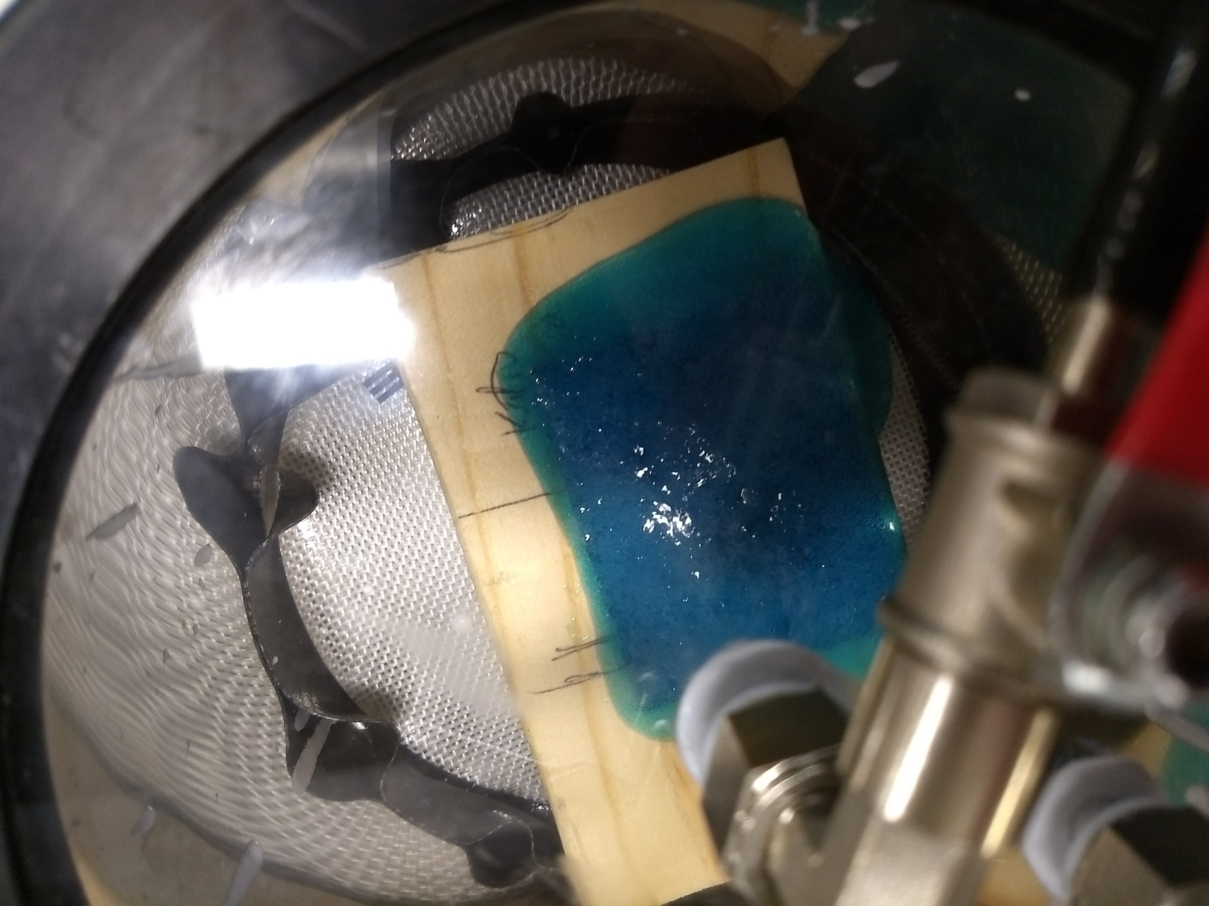
Mold in the vacuum bubbling
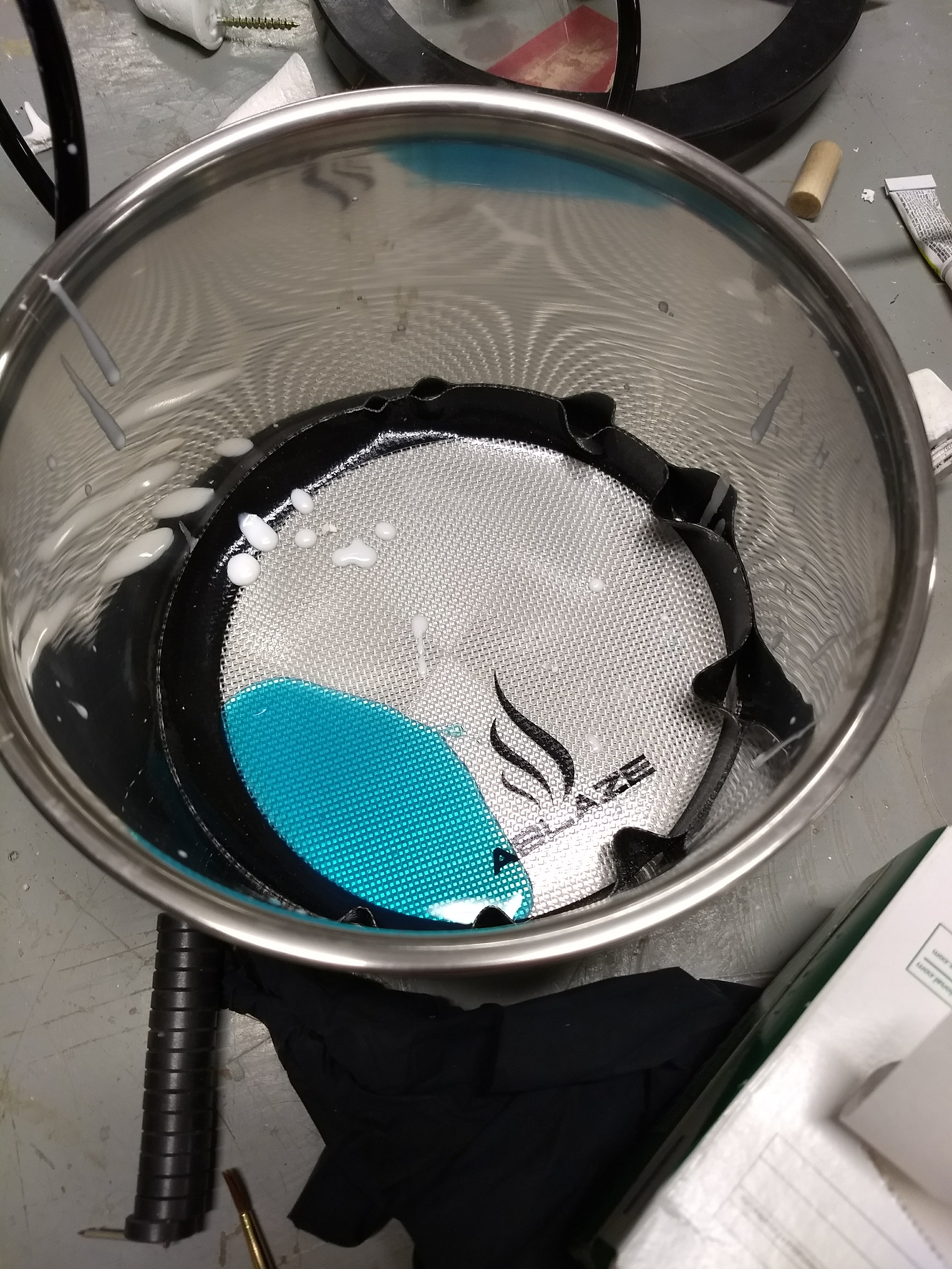
Silicone Mess
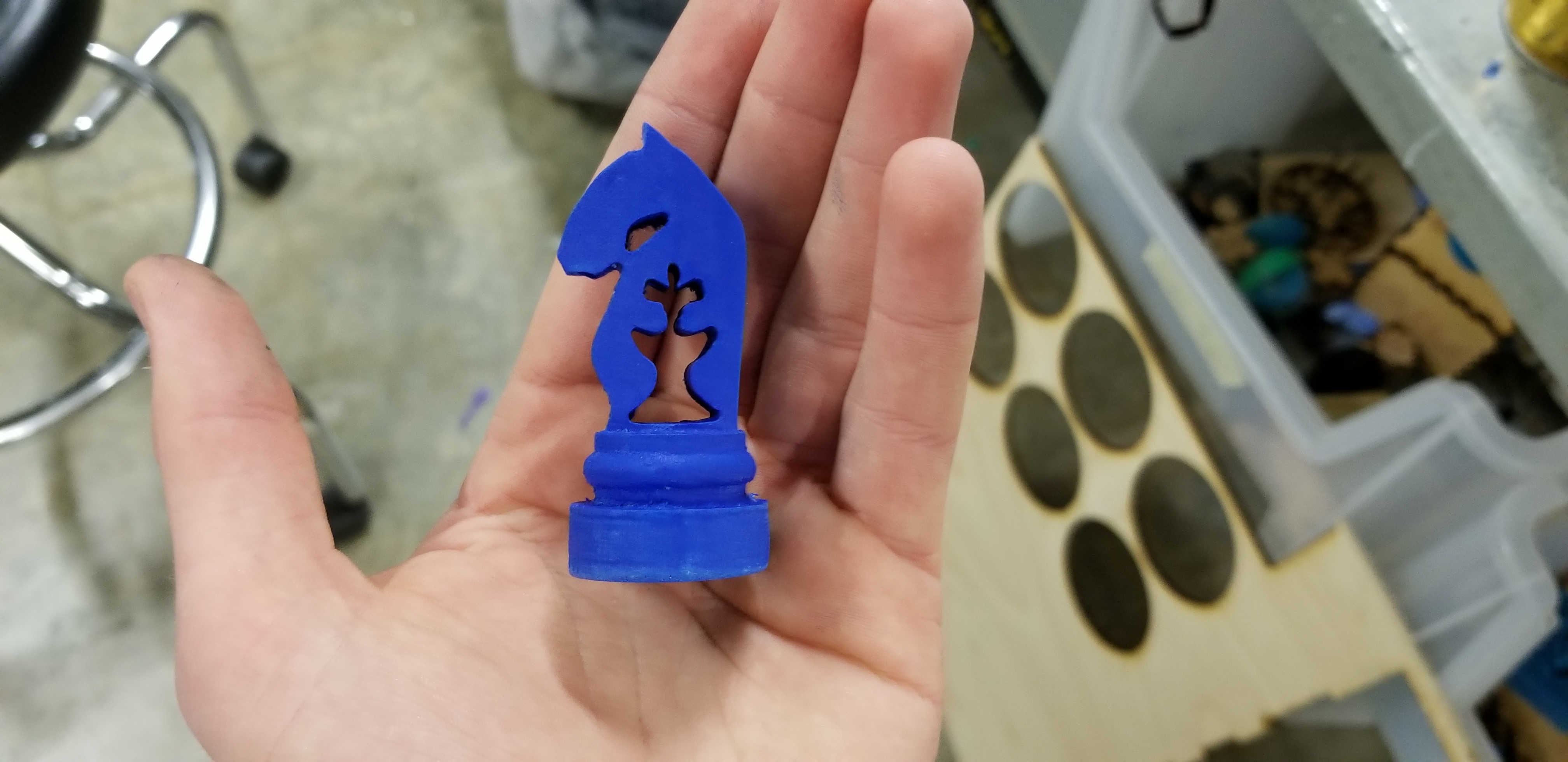
With multiple iterations of the negative mold prepared, we began to pour our final products. Each of the final pieces was made with EasyFlo with some added dye for color. We made a lot of different final pieces, attempting various techniques of casting. We found that using the smoothest of our negative molds made a noticeable difference in surface textures of the pieces. Additionally, swirling/shaking the piece, or vacuuming it, reduced the air pockets that built up. After many casts, we finally had two pieces that we were proud of, and we chose to finish those pieces.
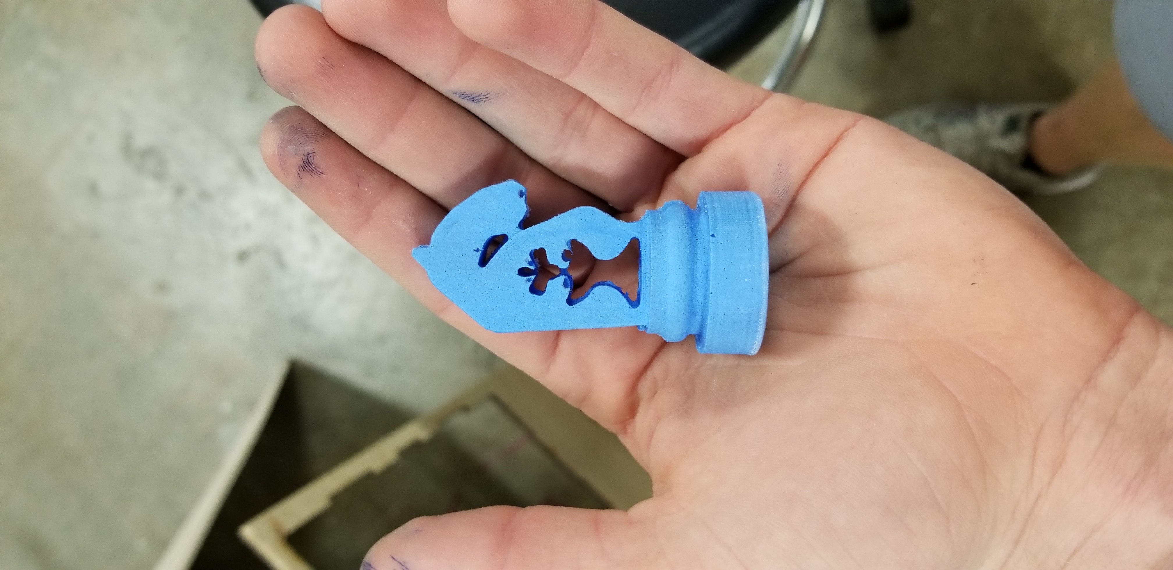
Less successful final piece
With our final pieces, we used an X-acto knife to remove flimsy excess material, and sand paper to smooth out the seams. We also used wire cutters to remove the air pipe that was attached to the piece. Once we finished with these post-processing steps, we were done!
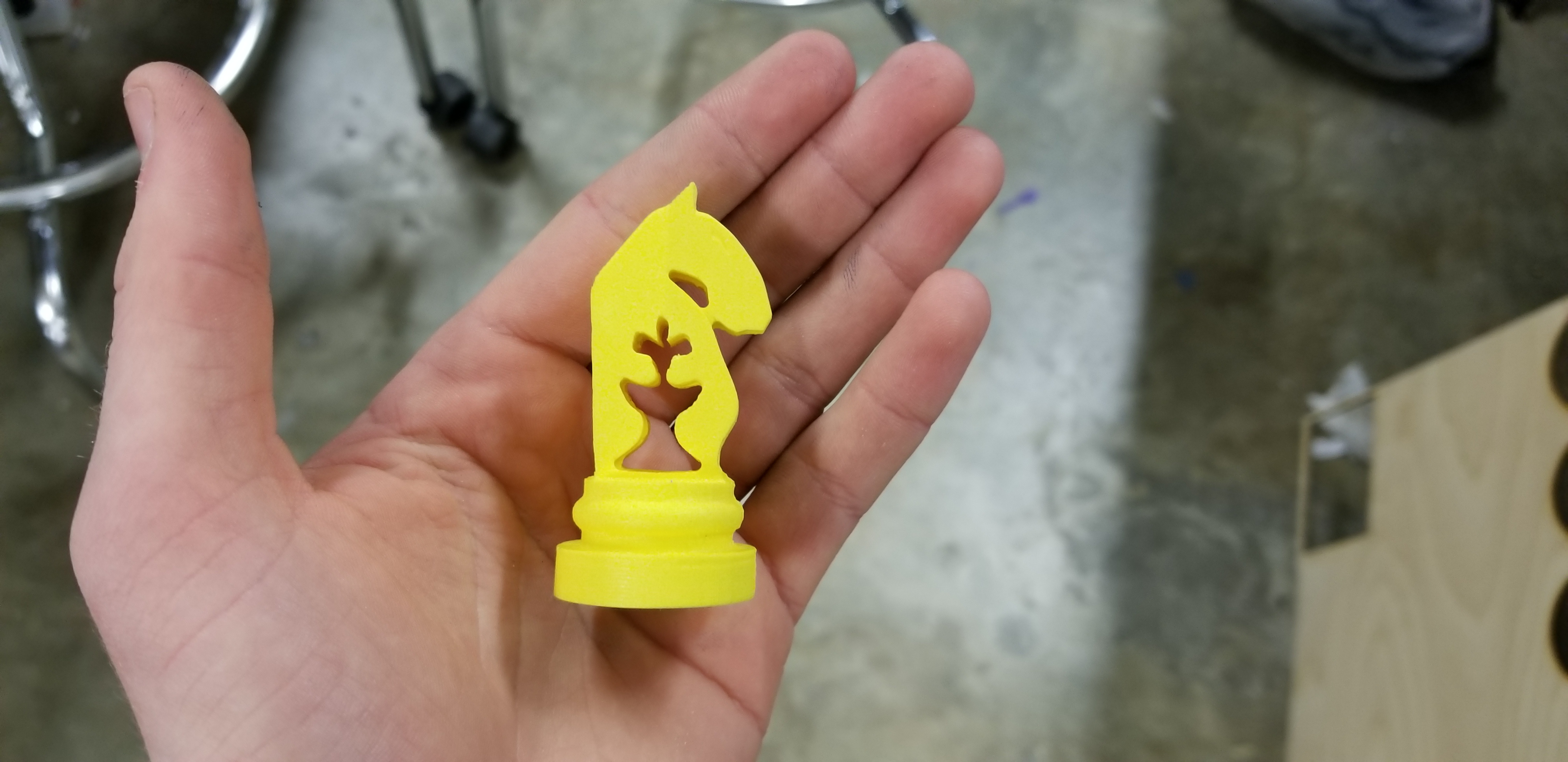
Final Pieces
– Nick and Josh
