It seems common knowledge, now trite in its ubiquity, that grades can cause in all levels of education a drive to pursue a number with least possible effort, instead of true learning with due effort. While the standards imposed by government and metrics demanded by workplaces and graduate programs continue to enforce this pattern on educators, it becomes the responsibility of the student to decide how to engage the system. For this project, I chose the latter path.
As soon as this project was described in class, a vision for my project immediately impressed itself upon me. The chance to intersect my musical background with my engineering degree to create a functional, beautiful machine was on I couldn’t pass up. Below is one of my early sketches.
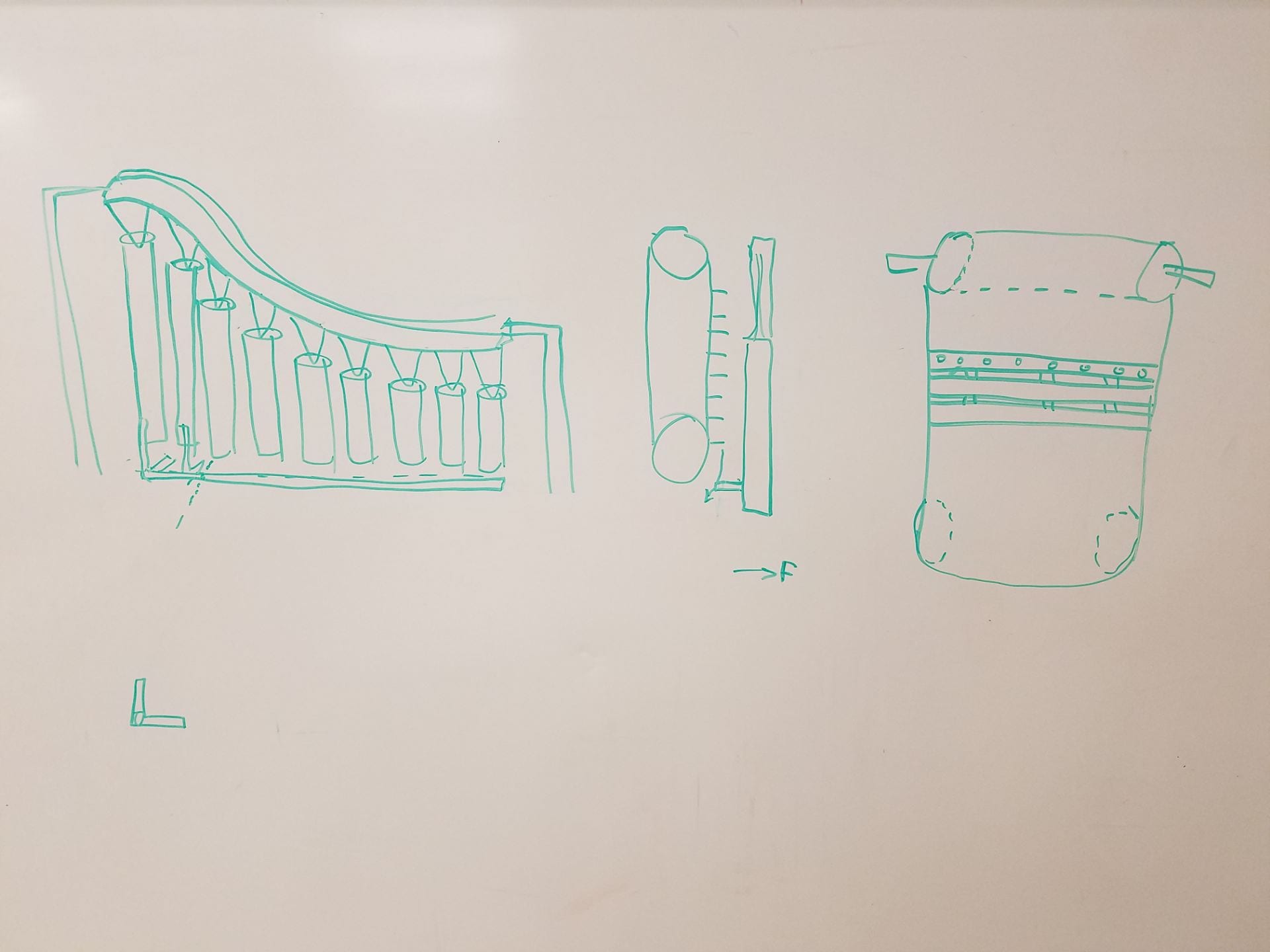
Figure 1: Early design sketch
As can be seen in the above picture, my original design involved wooden slats on some sort of tensioned belt system instead of a simple wheel. This proved to involved to tackle at present, but I created the opportunity for future expansion by leaving the top axle in my final design. I at first toyed with the idea of using vases of water to replicate the sound of crystal being vibrated through grazing of the rim. This proved too expensive, though, and the mechanism too complex. I still didn’t want to replicate the klinky sound of a normal music box or xylophone, however, so I opted for chimes instead. Recalling the high ringing, yet pure sound of wind chimes made up my mind. After some research, I decided on copper pipe for my material of choice, type M from Grainger: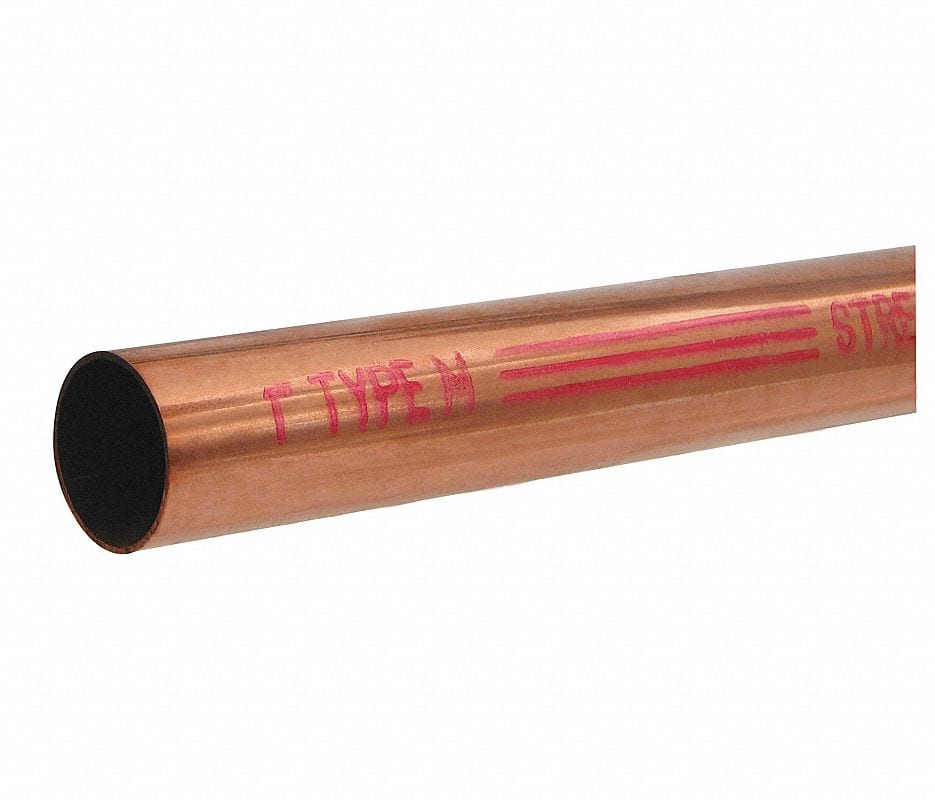
Figure 2: Chime Material
To decide what notes I would be using, I selected a song I wanted the box to play (Clair de Lune by Debussy) and the scale I wanted to play in based on the low note from the pre-fab chime set I had from my house (E). I cut these two lengths of 5 ft pipe into smaller lengths, approximately calculated with the following Matlab code:
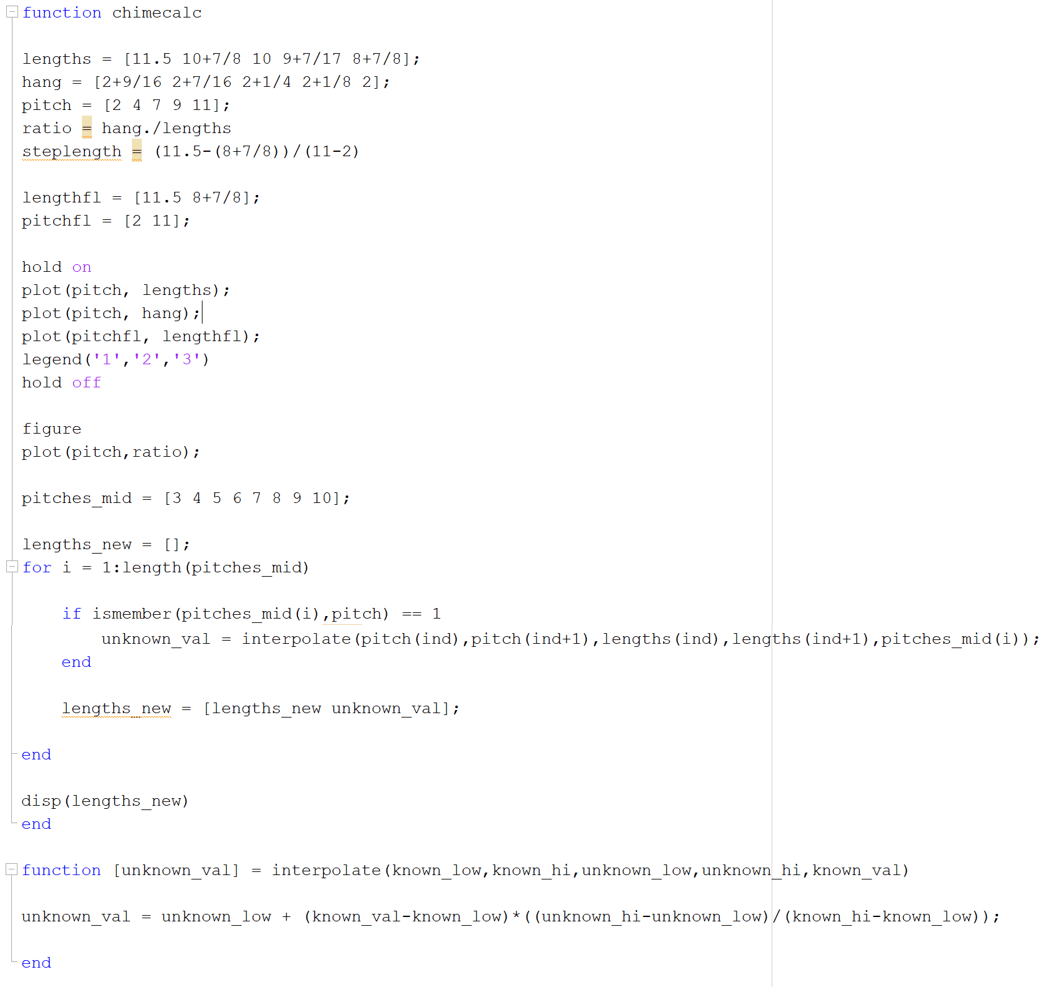
Figure 3: Chime length calculation MATLAB code
I cut each length about a quarter inch longer than predicted, then incrementally sanded them down with the belt sander in the machine shop until their pitch matched the desired one, played from my phone and compared by ear. I 3-d printed supports to allow me to drill horizontal holes through each, placed at resonance points I hand-measured for each length:
Figure 4: Pipe drilling stabilizer
After all the cutting and drilling was finished, I sand-blasted the tubes to achieve a much more visually pleasing matte finish:
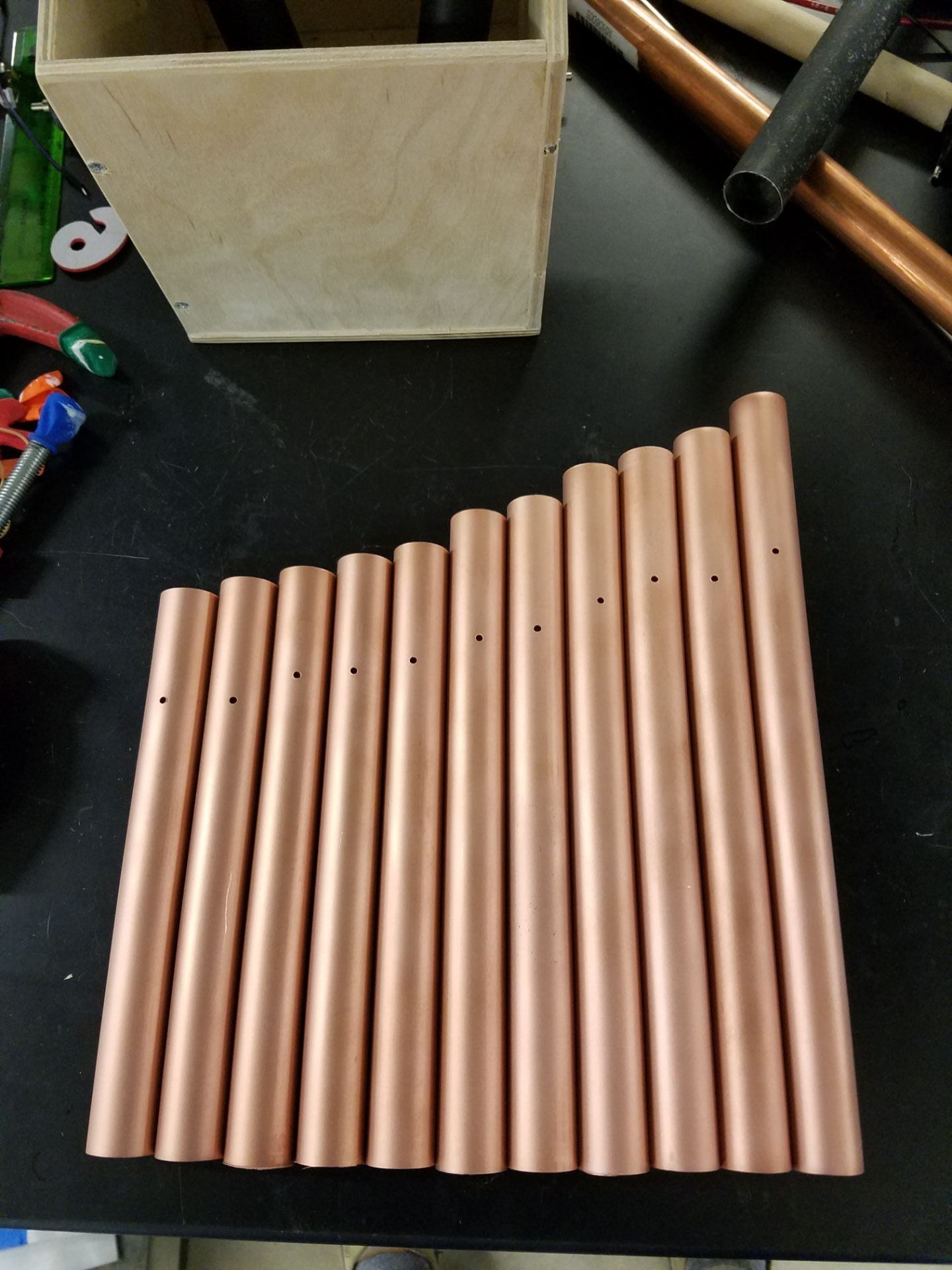
Figure 5: Finished copper pipes
Stringing the chimes up at our Senior Design table, I took a short break by treating myself to learning to play a tune on the inverted scale. Extra points if you recognize it.
Figure 6: Some relaxing music
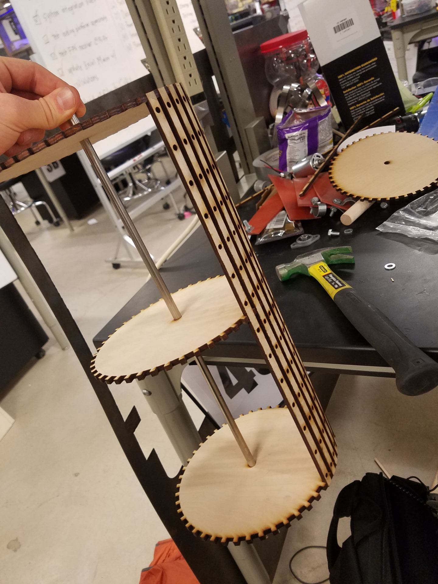
The chimes finished, I finally had specific height and width values to enter into my CAD design in Fusion 360. I updated my design for each prototype review, putting in real-world components and values as they became available (bearings, axle rod lengths, wood thicknesses, etc.). The most difficult part of this process was designing the correct tolerances into the geometries, as well as designing the adjustable side panel system with the laser cut steel inserts. The initial proof-of-concept CAD design took only a few hours, but nailing down all the specifications throughout iterative testing of the components took many more. I had to design my own finger joints for each intersection to allow for the laser’s current 6 degree slant. I tolerances the whole design to be assembled press-fit without glue so it could be taken apart and re-assembled if needed.
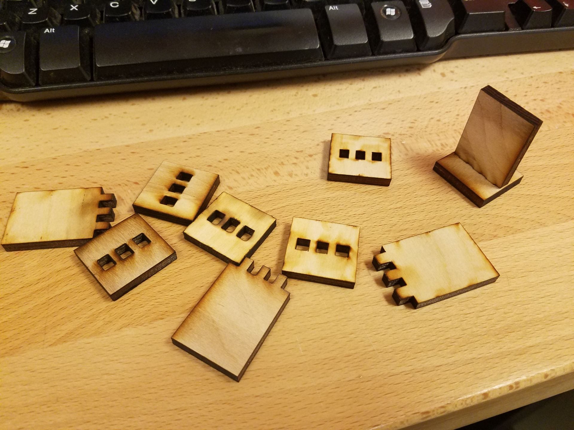
Figure 7: Finger and slot joint testing
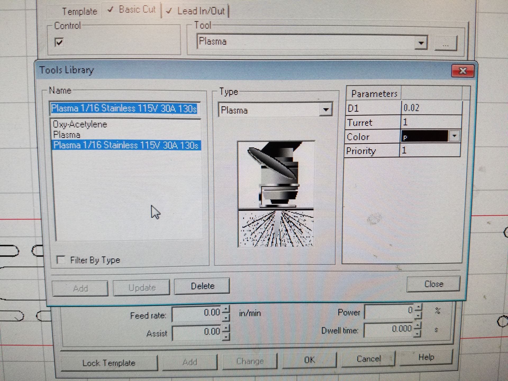
Plasma cutting the adjustable steel panels proved very challenging. I needed the holes to be fairly dimensionally accurate so that the M6 screws I chose would bind them properly. My first attempt failed because, following the plasma cutting instructions, I chose a male cutting path for the entire design. Giving myself a crash-course in the TorchMate software, I programmed in a custom kerf width for my particular settings and material, and specified a male path for the outer edge and female paths for the holes. My second attempt was a success. I ground off the slag and sandblasted for an aesthetic finish.
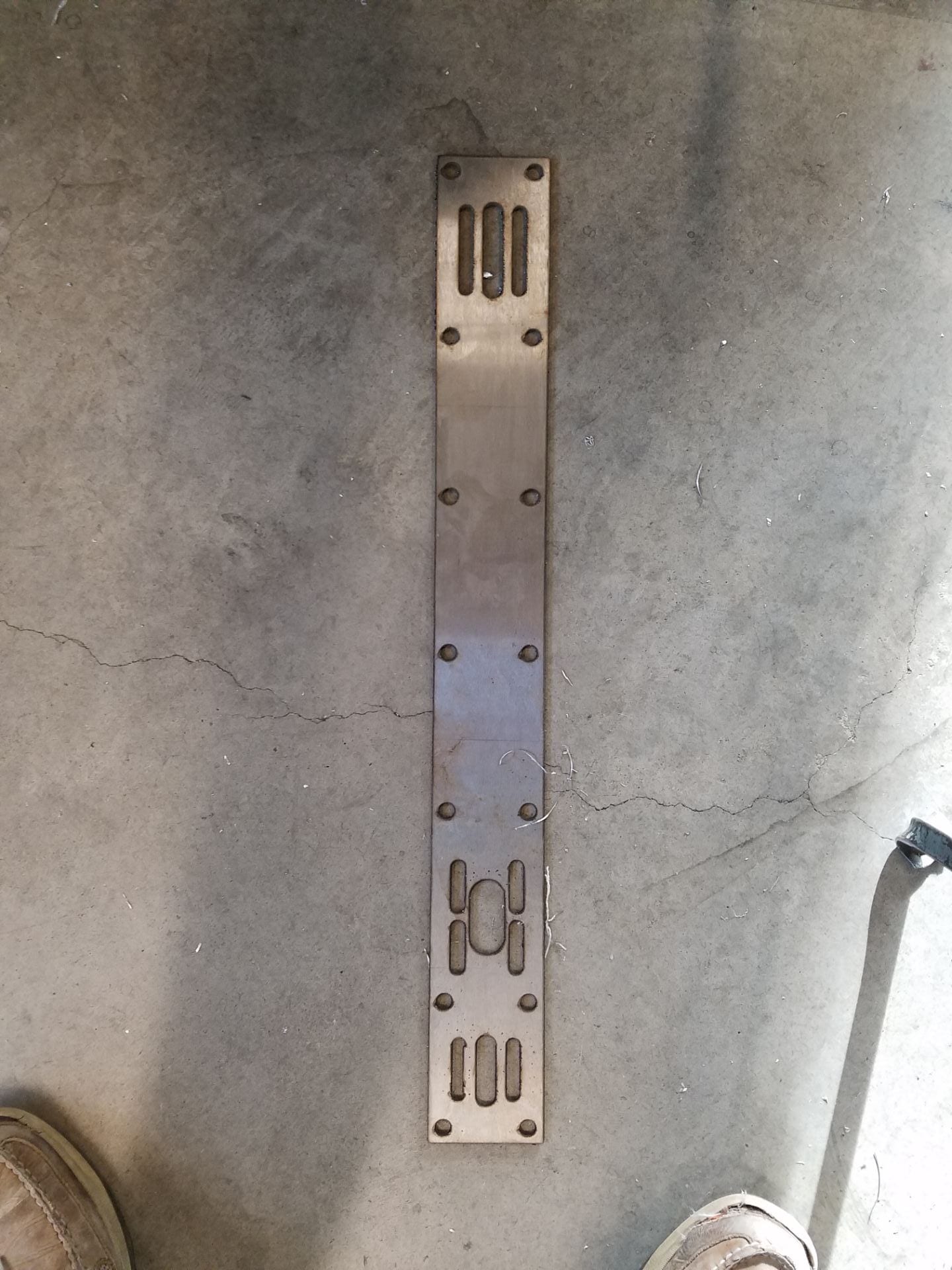
Figure 8: First attempt, cutouts are too wide.
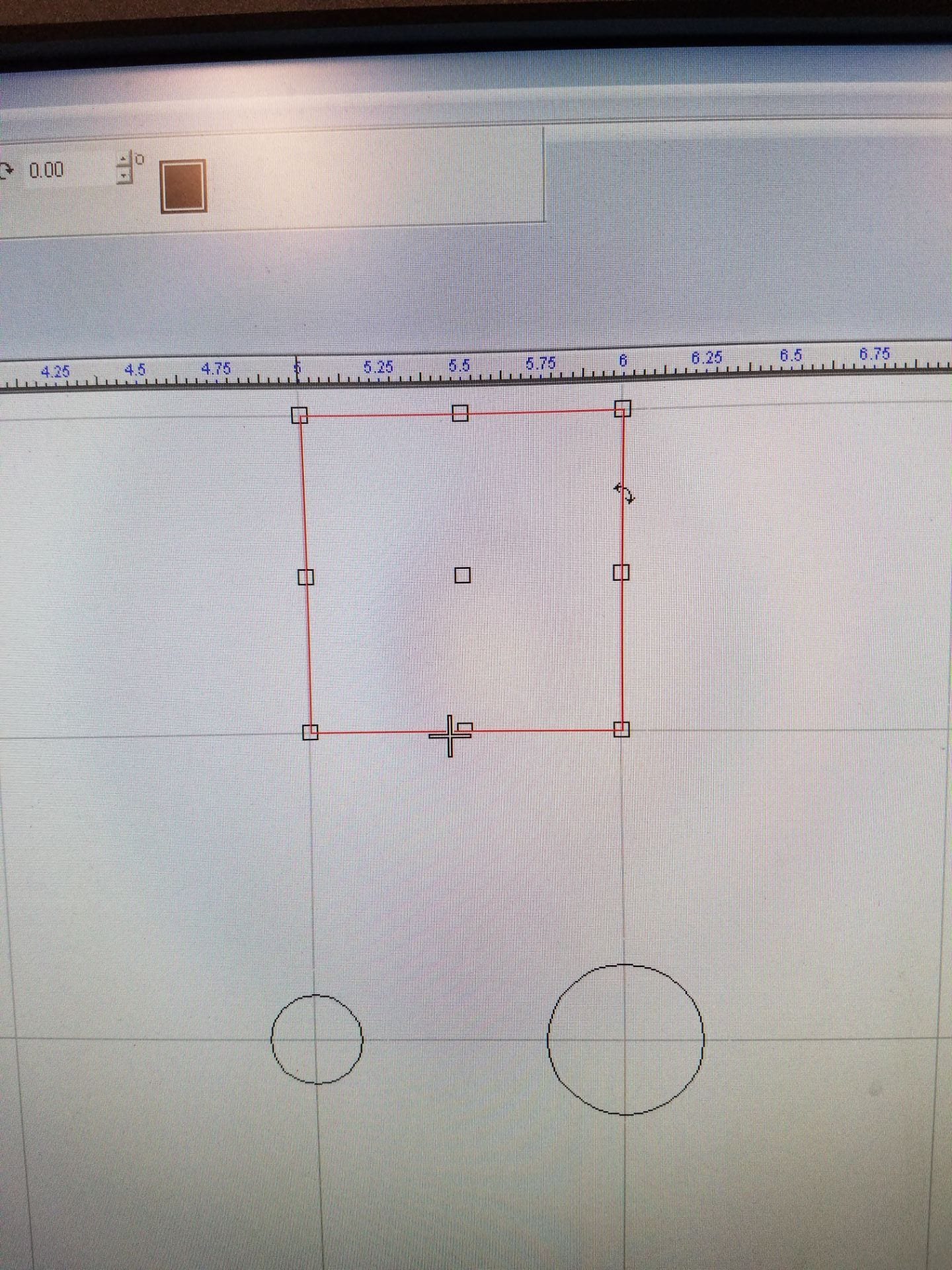
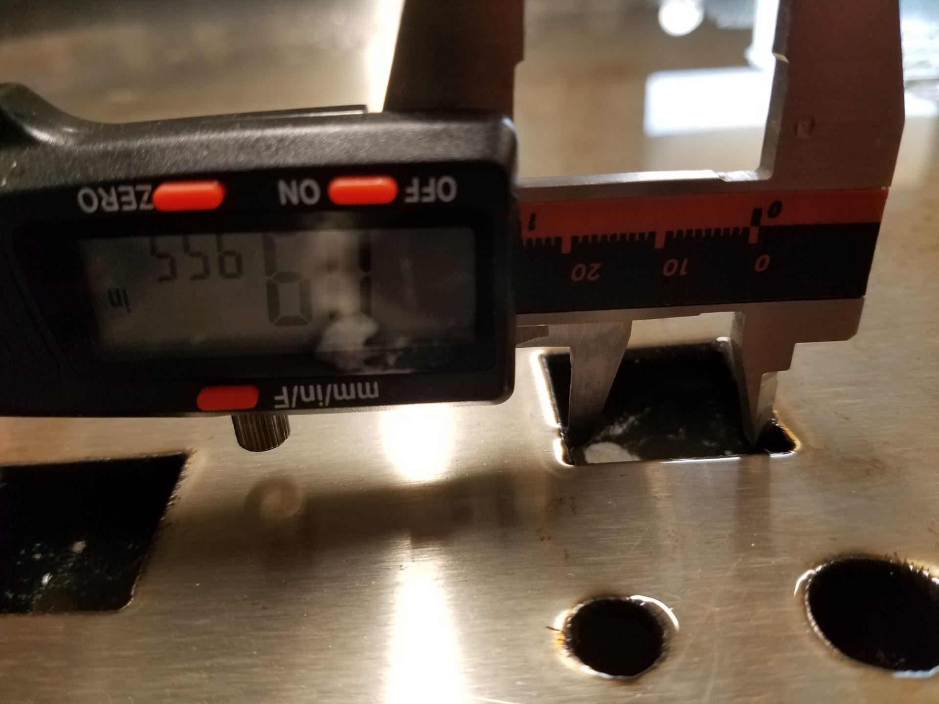
Figures 9-12: Experimenting with kerf width for more accurate cutout dimensions
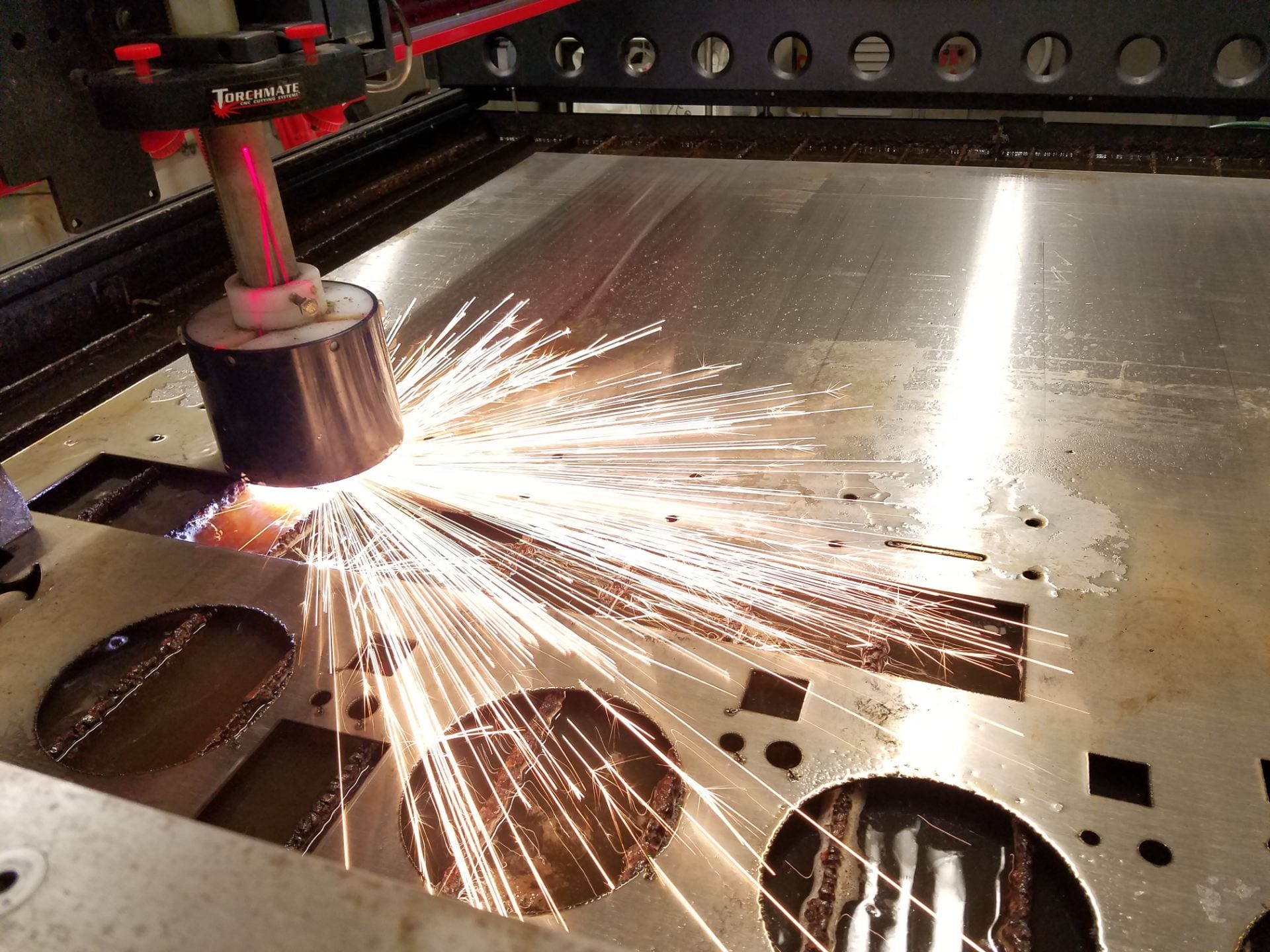
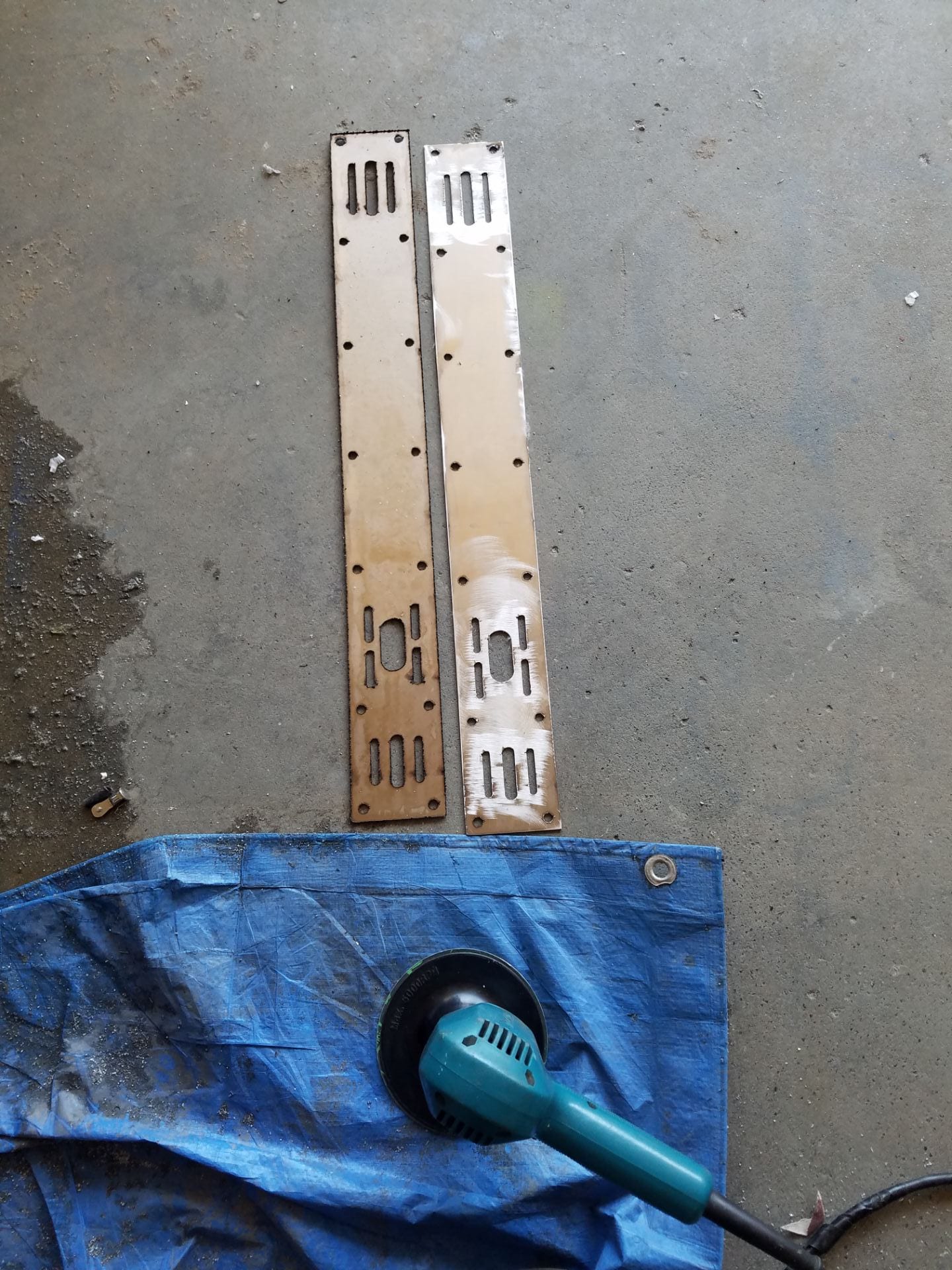
Figures 13-14: Final Plasma Cutting and Grinding
Finally, many hours of laser cutting ensued. Especially time consuming were the wooden slats for the music wheel, with their 45*12=540 small holes. Allowing the bilayered wooden side panels and base to dry flat also took time, since I had to weigh them down with lead bricks from the machine shop to mitigate the warping their source material had contained. Once I had all the pieces laser cut, it was time to begin assembly. I assembled the wheel first, which turned out to be my favorite part of the design and incredibly satisfying to complete:

Figures 15 and 16: Assembly of the music wheel drum
Figure 17: The result was mesmerizing when spun
Despite my best tolerancing efforts, I still had to file some of the finger joints. Soon enough however, after some more sanding and finishing, the frame was all ready to go.
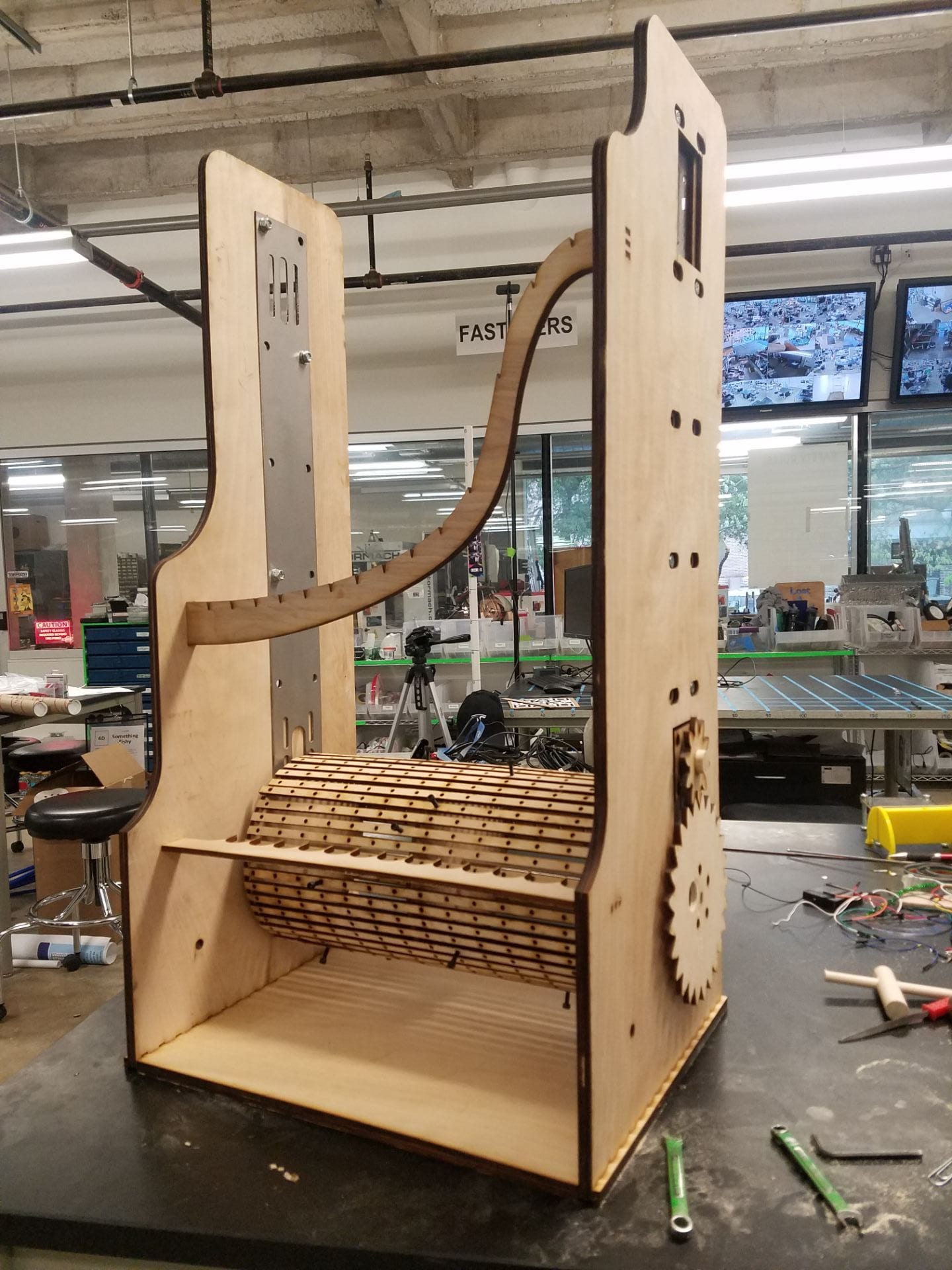
Figure 18: Frame Assembly
Next came experimenting with the hammer design, which I expected would take some iteration to get right. For the version I presented in class, I settled on a counterweighted design that relied on the motion of the wheel to propel the hammer into each chime. Finally, hanging the chimes: Though I wisely had designed notches at the exact correct locations in the S-beam, this process was still a huge pain. I found that simply looping string through the holes required string to lie against the side of the chimes, which dampened the sound considerably. I had to extend these loops outward away from the chime walls. To do this, I cut 2″ lengths of 3/16″ wooden dowels and threaded on corresponding nuts to compress the strings in place. I ended up wrapping my fingers in tape to avoid rubbing the skin off forcing so many tiny nuts to thread onto those tiny dowels. The fit was so close the nuts were actually cutting threads onto the dowels, shown below.
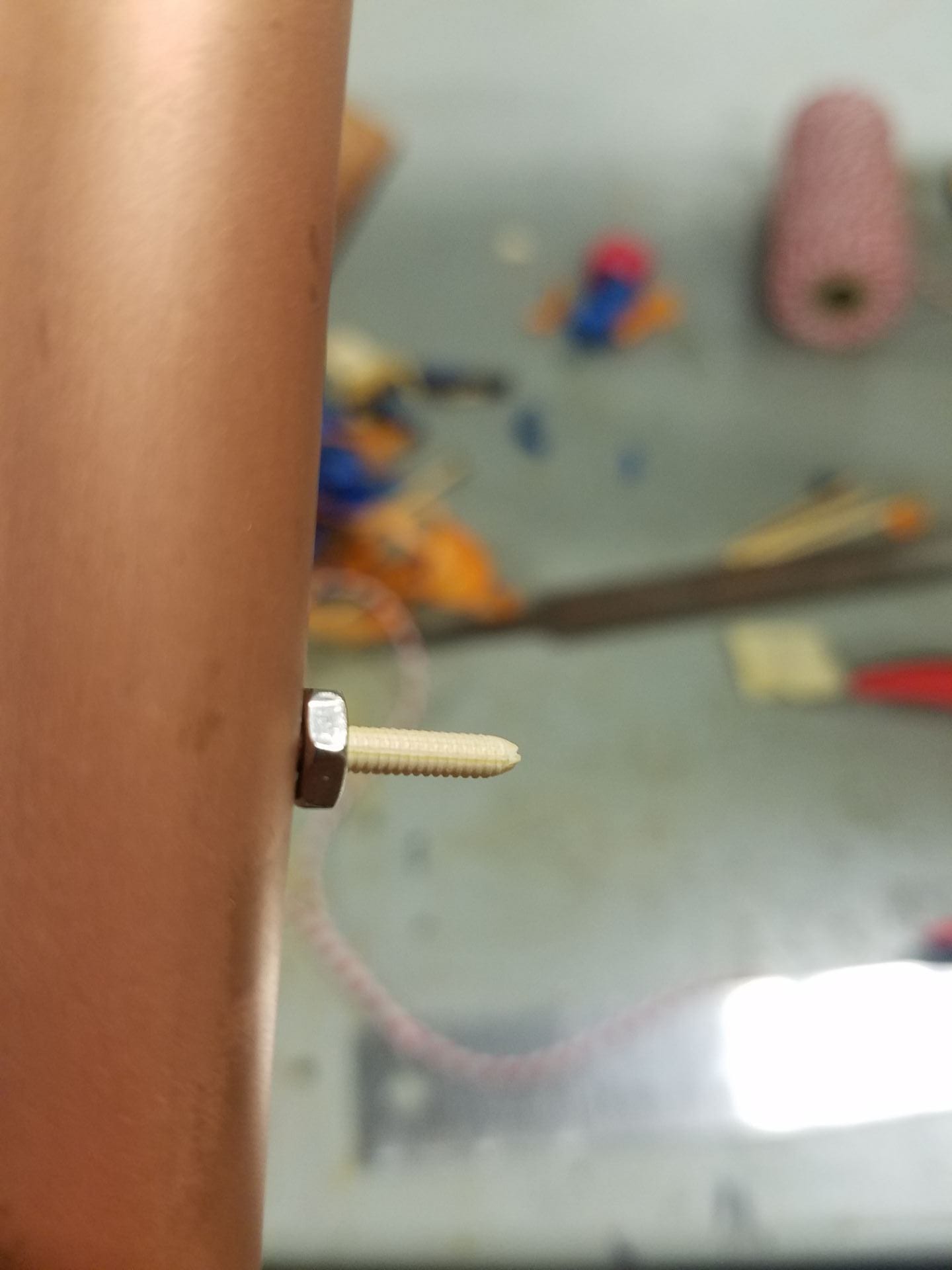
Figure 19: Tiny nut cutting tiny threads on a tiny shaft
Needless to say, as the process had to be repeated 12 times and each length had to be perfect so the chimes would hang vertically, inhuman reserves of patience were required. Luckily at this point I wasn’t feeling too human anymore so I taped and re-taped my fingers and pressed onward. Finally, all the tubes were hung.
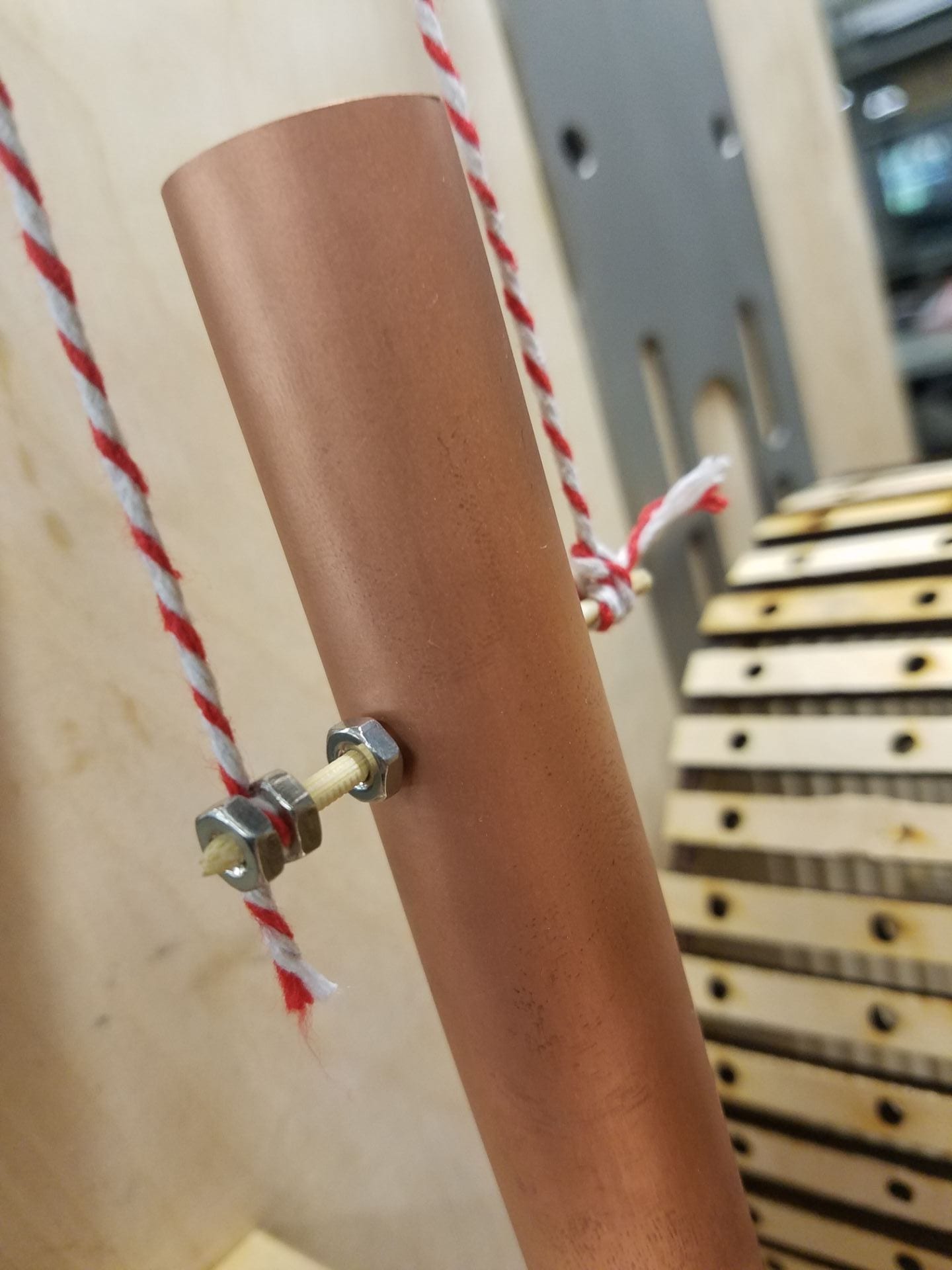
Figure 20: Closeup of hanging mechanism
Placing the wooden pegs/socket head screws in the appropriate holes on the music wheel was as simple as transposing Claire de Lune from D flat major to E major, then condensing all the notes into a 12 note scale. I edited the music in NoteFlight, then lined up the notes using a labeled slat to place pegs in their proper place. Each slat represented one eighth note, and the piece being in 9/8 time, I was able to fit 5 measures of music onto the rotating drum.

Figure 21: Placing the pegs
Lastly, I had to redesign my hammer system. Relying on the wheel motion proved too weak to generate a good sound, so I had to design a way to allow gravity to provide the motion. I had tested this before and rejected it because flipping the direction of actuation meant that in the resting position, the hammers pressed against the chimes, dampening all reverberation. I returned to my drawing paper and had a solution before long. I figured that at this point, I may as well make things look cool too, so I designed the hammers to look like music notes and the cushion stands to sport a row of violins when standing abreast.
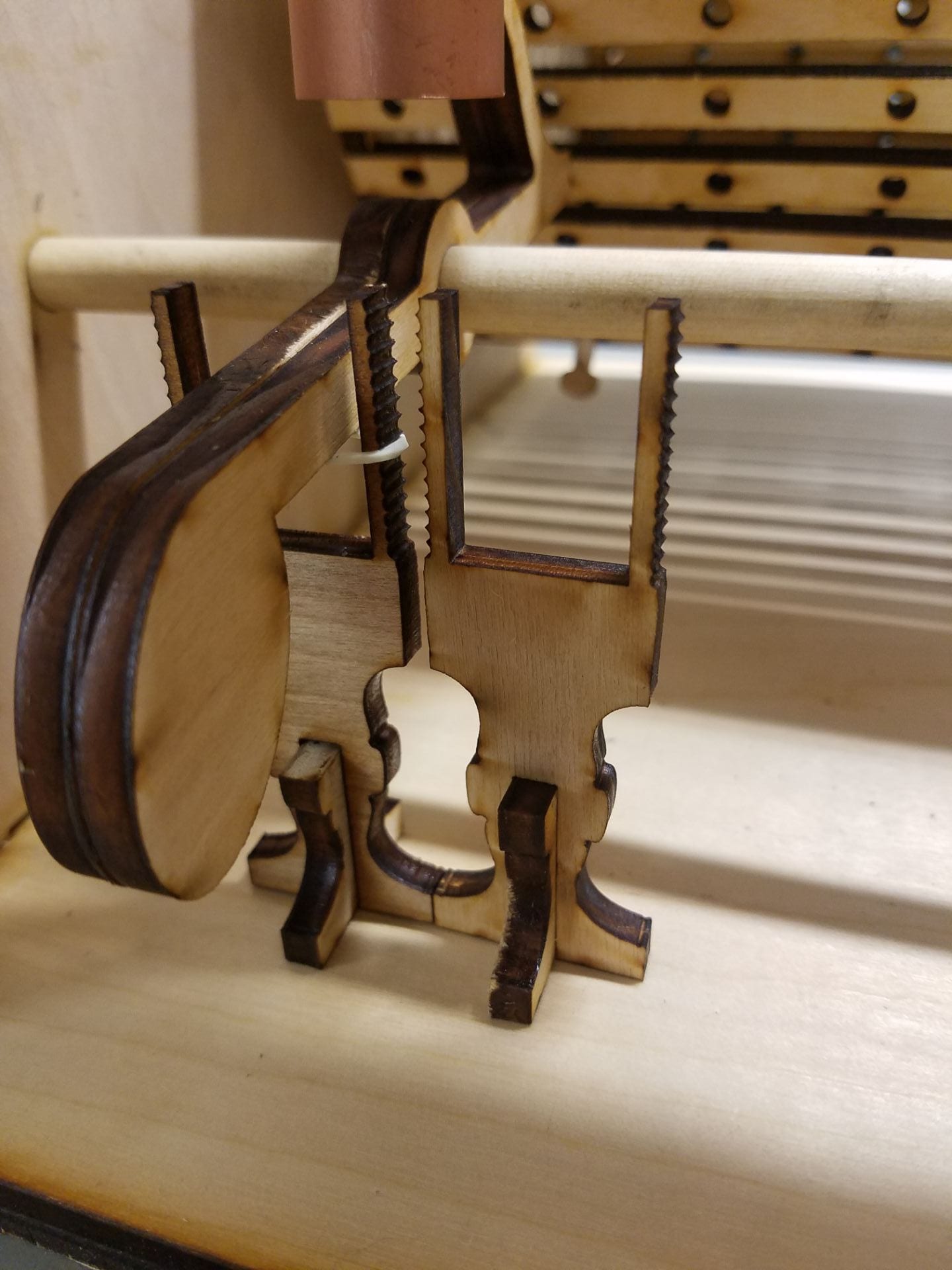
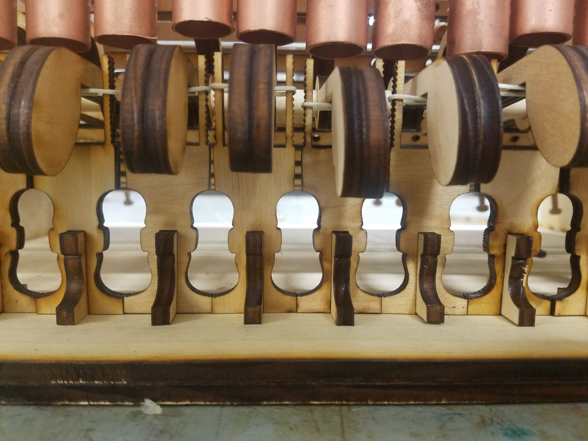
Figure 22: Violin cushion stands and eighth note hammers
I was glad I designed the stands with adjustable notches, as this feature proved very useful when fine-tuning the hammer zero position for each chime. With the chimes hung, rubber bands at appropriate heights, and everything assembled, my vision was at last complete.
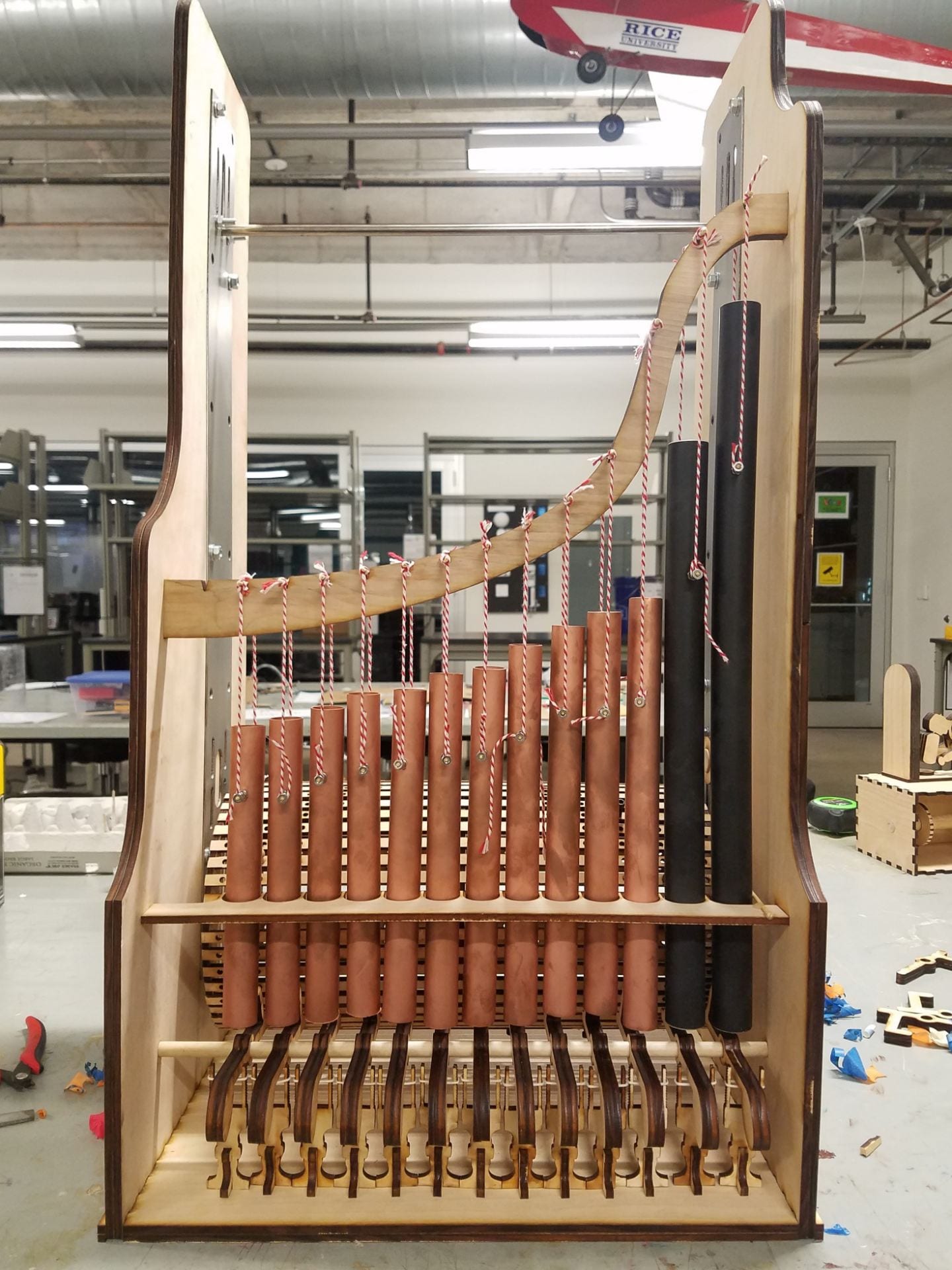
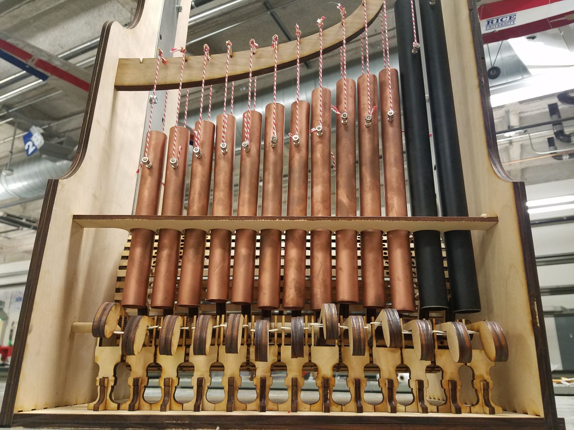
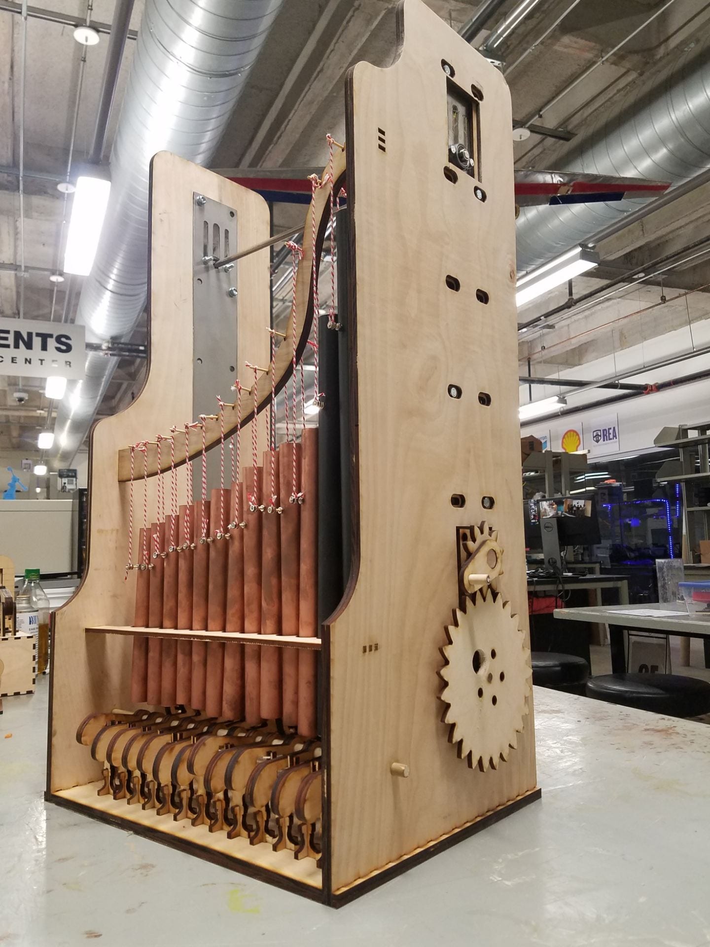
Figures 23-26: Completed Music Box
Though my grade won’t reflect it, I learned a vast amount from this project. At some points I was teaching Joe things about the plasma cutter, I became intimately acquainted with my friend the laser cutter, and almost learned not to hate Adobe Illustrator. Almost. I got to exercise my CAD skills further, without which this project, with its tight tolerances and finely balanced moving parts, would have been all but impossible.
I should note as I conclude that I was warned many times along the way that I seemed not to be as far along as I should have been to complete the project on-time. Though I did make a conscious decision each time to charge forward with the project whether I would be able to complete it on-time or not, there is something to be said for choosing a project of adequate scope for the assignment at hand. If I were allotted a certain amount of money or time in the workplace, and I chose to ignore those and pursue a project requiring more of each than given, I would likely be fired. Now, although the objective in the workplace (maximizing money, which in that metaphor did not occur) is different than that of a classroom (maximizing learning, which in my situation did occur), it is still important to practice those time management and self-discipline skills while still in school. I felt in this case the vision I had demanded I break out of the box a little to satisfy my engineering creativity. However, in the future I plan to strive, as I usually do, for a better balance there.
