For this project, we worked to create a functional “carrot slicer” using the mechanism 24 and 63.
Gate 1
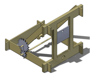
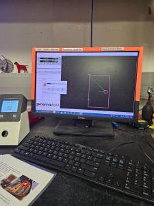
The purpose of gate 1 was to develop the initial concept. We decided to do this through Solidworks as it would mean the design could be changed more efficiently, and the parts could be put together virtually into an assembly to ensure the sizes were appropriate before cutting any wood.
To cut the pieces we designed, it is possible to save a Solidworks file as a .dxf file, which can be brought into Adobe Illustrator to prepare for the cut. This works for both Solidworks sketches and parts, as it creates the sketch based on the desired view of the part.
The Solidworks assembly had the gears and metal blade connected to rotate and slide as expected in the real world.
The initial gate 1 design included a winch that was not utilized in the following few prototypes but became a last-minute addition to the final prototype that will be described later.
The dowels used are all 0.25 in diameter, although this was changed after gate 2 as we realized the dowels were deflecting too much.
The side brackets and cross brace in the back were all increased to triple the thickness as it was necessary to take the load of the blade.
Gate 2
The goal of gate 2 was to begin actual prototyping and create a low fidelity prototype. We began by taking our Solidworks files, adjusting the files accordingly for the materials we were using (primarily cardboard), and saving them as dxf drawing files. We then laser cutted out the files with the appropriate settings (the recommended settings on the wall) for cardboard. This process was repeated several times to give us 3 cross braces and 2 side brackets.
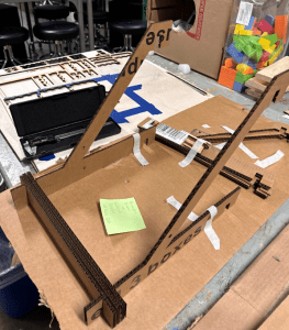
We then repeated this process for the tower pieces with the exception of using wood instead of cardboard. We opted to go ahead with the wood over cardboard as these parts were essentially where the main movement of the project occurred (blade sliding within the tower). Therefore, we wanted to ensure as soon as possible that our dimensions were correct for the material we planned on utilizing in the end. This meant we also needed to create our blade to test the fit within the tower and the smoothness sliding up and down. We choose to utilize the waterjet cutter over the plasma cutter as we don’t hate ourselves (the waterjet is simply easier and more time efficient). Once again, we created the part in Solidworks, downloaded the dxf drawing, and opened/uploaded it on the waterjet computer. After finding a piece of metal with the right thickness (.2”) and setting it in the cutter, we worked through the software and began the cut.
After cutting all of are pieces, we began assembling the prototype. We also acquired two .25” diameter, wooden dowels as well as fishing line. We opted for fishing line as we believed it would be stronger and less likely to snap from the weight of the blade compared to a regular string/thread. After fully assembling the prototype, we tested it to see if it worked and if there any clear issues. The piece proved to be successful; however, we noticed that the dowel that was pulling the string was experiencing significant deflection. This would lead to a few changes within our design (thicker dowels, two strings instead of one lifting the blade) in our next iteration.
Gate 3
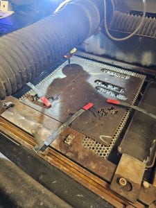
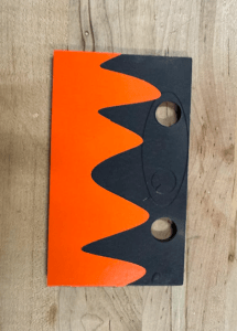
One of the first improvements we made for gate 3 was to cut a new blade with two holes for wire. The hope was that with two holes, the blade would be lifted without tilting and possibly binding, as was occasionally seen on gate 2. In an attempt to conserve metal, we first tried to modify our already cut blade to have two holes, but because we could not zero the piece properly on the waterjet cutter, the extra holes were slightly offset from the centerline.
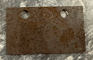
After the failed attempt, we cut a new blade out of a larger piece of metal, and the result is shown below. We did not realize that a design was partially cut on the back side of the stock material, but we hoped that it would no longer be visible after the sandblasting and powder coat. Only the sandblasting was done for gate 3, with the powder coat added afterward for the final prototype.
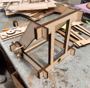
We also cut a new fully wooden structure with thicker side brackets, although this design had incorrect slot dimensions, resulting in a loose fit. The side brackets also contained the correct hole diameter to press fit bearings for a thicker axle. The hole diameter necessary for the bearings was determined by cutting many different diameter holes into a scrap piece of wood and checking if the bearing had a snug fit.
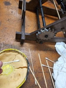
Gate 3 also included the first gears to be cut, and the hole diameter inside each gear was based on the diameter of the dowel it was meant for. A press fit was not desired here, as we felt it was necessary to epoxy the gears to the dowel to sustain the load of the heavy blade.
Final Prototype
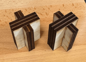
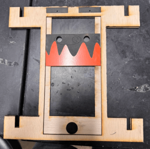
The first change that had to be made for the final prototype was to ensure that the structure did not have a loose fit. We started by making test pieces representing the slot we wanted to use, but with different slot widths, to find what values resulted in the desired press fit. We found that the best method was to first subtract 0.01 in for every 0.2 in thick plywood piece in the part, then subtract a finally 0.005 in to the entire slot width, resulting in the perfect fit, where it was strong enough that we did not include any wood glue or epoxy in the structure.
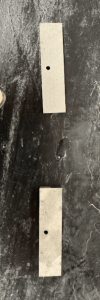
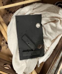
Next, we had to tackle the fact that the fishing line would dig into the wood when under load. We designed two metal “ hooks” that the wire would rest on while it was in tension so that it would no longer cut the wood. These were designed to fit inside the middle tower portion. They were cut from the waterjet, sandblasted, and had a black powder coat finish applied to them.
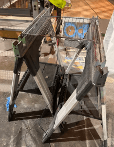
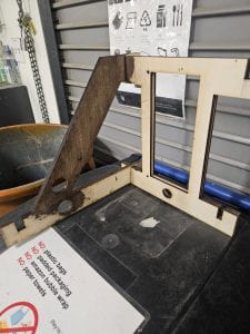
The powder coat process was straightforward for the blade and two hooks. A picture of the process is shown below, where the pieces are hanging from the rack using paper clips connected to the holes.
After the powder coat had cured, the orange vinyl pattern was added to the blade. This process was simple as we had done a few tests using a blue color.
We then began staining the frame of the project as well as the gears with a special walnut stain. When choosing our stain, we used an older prototype to test and see how it would look, ensuring that we would be satisfied with our choice.
Furthermore, to ensure that the slot for the blade wasn’t interfered with, we covered it with masking tape to prevent strain or anything from getting inside. We followed instructions on the container throughout the entire process and let pieces sit for 12 hours. During this time, we began to prepare the wood dowels. This essentially meant cutting the dowels to an appropriate size as well as drilling holes into one of them to allow use to tie the string through.
Once everything dried, we then assembled the all pieces together and tested our project. However, our project failed to work as the blade would be stuck at the top of the tower due to a combination of factors: friction between the line and steel holders; the dowels being slightly bent, thus applying a side force/load to the ball bearings and reducing how smooth they rotate; the moment of (inertia of) the bar; friction/tension between the gears. In order to fix these problems, we took several actions and altercations to our prototype. However, we didn’t take these actions all at once as we didn’t realize all of this issues were occurring at once. We, for the most part, learned about the issues one by one as we continue to alter and improve the final prototype.
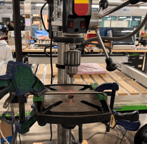
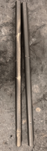
To begin, we applied several lubricates to the line and steel holders. After appearing to have little effect, we then talked to Joe, who used a bevel on the steel holders to create smoother edges. He also recommended that we switch to a thread, since it has a smaller diameter and would slide better. In addition, he also pointed out that our dowels were not completely straight and explained how that affected how smoothly they could rotate. He gave us a straight, hollow 0.5” metal rod for our use. After cutting the rod into 2 pieces of a desired length as well as sanding them using the sander in the machine shop, we inserted the rods into the assembly and used a thread instead of a fishing line. We then did a test run, which performed well. As a result, we then began post-processing the metal rods, which included drilling into one (to attach the thread through), sandblasting each, and spraying each black.
Once everything dried, we then re-assembled the prototype and attached the rods to the bearings and the gears to the rods. We accomplished this by using epoxy. We also worked on the dowel holding the ratchet peg by cutting it to size, laser cutting press fit holders to keep the dowel and the ratchet peg from shifting, and staining it with the same stain from before.
After letting the epoxy harden overnight, we once again tested it and it once again failed by getting stuck at the top. After receiving feedback from the teaching staff, we aimed to reduce friction between the gears. We discussed with Joe about potential lubricants to use, in which he recommended wax as any oil-based lubricant would most likely get absorbed by the wood. After testing a few waxes on a block of wood for testing, we began to apply wax to the teeth of our gears.
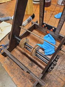
After applying the wax, we tested the project, in which it got stuck at the top. Joe recommended that we put some kind of wheel on the rod and attach the string to that as, due to the greater size/diameter, the moment would then decrease and make it easier to spin. Joe had actually suggested this idea initially; however, after conducting our successful test run before metal post-processing, we thought we wouldn’t need to. We continued to avoid this idea as we had already glued everything together with epoxy, thus we would have to undo that in order to attach a larger diameter wheel. However, it became very clear that we would have to increase the diameter the string was wrapping around. Since the rods and gears were already epoxied, we decided to create our winches in half as this would allow us to place and glue the pieces together on the rod. We laser cutted two circles with an outside diameter of 2”, and four circles with an outside diameter of 2.5”. All pieces had an inside diameter of 0.5”. We then glued the two of the larger circles to the sides of a smaller circle.
Once the glue dried, we then placed the two halves together with the rod in the center and used epoxy as well as a heat gun (to cure the epoxy faster) to attach the winch. Once both winches were attached and dried, we then attached thread to both winches (using epoxy) and the blade (simply knots). Finally, we conducted one more test, in which our prototype worked successfully.
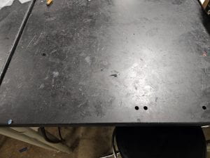
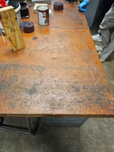
Clean Workspace
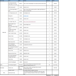
Cost Estimate
Link to our presentation slides
