First up is Avinash’s project. About halfway down the post is David’s.
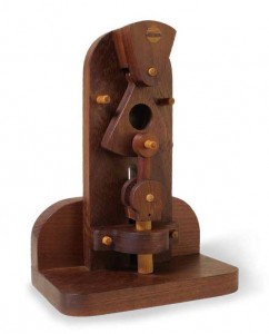
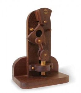
My project was derived from my 2D Drawing assignment. In that assignment, I modeled a harmonic oscillation punch machine from the Building Wooden Machines book provided by Dr. Wettergreen. Basically, what this is is a hole-punching-type mechanism that builds upon and operates along the principles and concepts of harmonic oscillation. Quite honestly, I do not believe I truly understood what the mechanism was until I had actually cut and assembled it. The mechanism and its operation were a bit difficult to visualize without a physical model. What happens is that the user displaces the pendulum, using his/her finger, and a link is consequently rotated to displace yet another component that is connected to a large dowel that will punch through the base. In my opinion, this is not a very effective project to be done in wood, but doing it in metal with the resources at our disposal would be much more difficult. So, although it does not serve the explicit function that its name suggests, it still provides a fascinating mechanism to observe. The pictures below give a fairly good idea of what goes on in the mechanism.
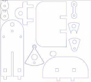
After the 2D Drawing assignment, my part was definitely not ready to go to a laser cutter as most of the shapes were either misshapen or horrendously dimensioned (probably a millimeter or a half in discrepancy for dowel holes). At first, I tried to re-draw the parts in Adobe Illustrator, but I soon determined that my sketches were not salvageable if I wanted a clean and sleek laser cut assembly. My first task, then, was to re-draw my outlines for the punch machine. I decided to go the more familiar route and used SolidWorks’s Drawing tool to re-do all of my sketches. There were two reasons for my use of SolidWorks over Adobe Illustrator for this purpose: I am more comfortable using SolidWorks, and SolidWorks is made for dimensioning, as opposed to Adobe Illustrator, meaning my parts could actually be properly scaled as according to the book’s specifications. Additionally, SolidWorks can also export files as “.ai” and “.pdf” file extensions. My drawings came out much more satisfactorily this time around, with relations between different components being more accurate and appropriately scaled. The first picture below is from the same file as my submission of the 2D Drawing assignment. The second image is from my finished first draft of sketches in SolidWorks. In the SolidWorks sketches I ended up adding a design for the base- and backboards, as they were not originally included in the list of profiles that was provided in the book; these two pieces were included in the overall assembly of the punch machine later on in the procedure laid out by the book and provided a great level of stability to the system when it stood, after cutting.
In the first cut, essentially everything was just too big. This included the holes for the dowels, especially. I didn’t really realize this until I attempted a rudimentary assembly and saw that the dowels had more than enough (i.e. too much) space to move about within their holes. No amount of glue could have really fixed this scaling issue. Additionally, some of the hole alignments did not correspond to their counterparts in other pieces. Also, Dr. Wettergreen recommended that I replace some of the dowel holes with notches so that I could simply ‘press-fit’ the pieces together. This seemed like a feasible idea for several of the pieces but not so much for others. For a number of pieces, I ended up adding my own notch matings onto the pieces I had already designed. For all of these initial changes, I took note on these pieces and corrected them in further drawings.
For the second cut, after dimensioning some things that were wrong from the previous iteration, I had forgotten to remove my centerlines from my SolidWorks file, so the laser cutter also cut those. This effectively cut a majority of my pieces in halves. I had not thought much of leaving in the centerlines because SolidWorks always ignores them as imaginary reference lines.
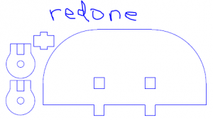
And, just like that, as they say, ‘the third time’s the charm.’ The third time I went in to cut, I managed to get pretty much all of the pieces and sizes and shapes that I had wanted. Some things I came in to redo because of a small change here or there (e.g. the piece did not fit quite as well as I would have expected or it is slightly too large or small for the notch it is slated to enter (see image below)), but essentially everything was up to my standards in the end. Then, I assembled everything, using glue where needed to fix some joints and dowels in place. Many things just happened to click or wedge into place though. For the pieces that fit perfectly and tightly together, I felt there was no need to re-cut them. I ended up layering almost all of the pieces twice for the sake of aesthetics and stability as well as for dimensioning. As the thicknesses were not deliverable as specified in the book, I came up with my own ratios for layering thicknesses between different component parts. I also needed to drill a 1/2-in. diameter hole into the base-board, as specified in the book, through which the punch mechanism could traverse; I did this with a drill press. I then sanded down several pieces for smoother, less frictional contact forces.
My final assembly appeared to function quite satisfactorily to me. It appeared similar to the pictures in the book and functioned as it should. It also has several parts that are firmly wedged together but can be removed for the sake of maintenance, interchangeability, or refinement. This would include the punch dowel itself, and this could potentially work in such a way that several different sizes of punch dowel may be used with some modifications. Additionally, many of my pieces appeared quite singed after the second iteration. I tried to remedy this by making two passes on a lower power level; however, this only made things worse (or so I thought). At second glance, I think that, because the singeing does not structurally hinder the stability of the assembly, the singe markings give the appearance of some of days of yore, an antique, if you may. It appears to give the final product a more rustic look, as though it may have been used many years ago. For a machine such as this, I feel that this is quite appropriate, so I did not try to re-do any parts from here.
For our second project, David laser cut and assembled the Oil Pump-Jack from his 2D Drawing assignment:
To begin this project I went back to my Adobe Illustrator files of the pump-jack and compared my parts to the final product shown in the workbook. After analyzing the final product I found that there were a few pieces that had not been included in the parts and dimensions page of the workbook, so the first thing I did was create these missing pieces in illustrator. The completed 2D drawing can be seen below.
Next I cut the pieces for the pump out of 3/16″ plywood with the laser cutter. Most pieces needed to be cut twice, either to be glued together to add thickness, or because a part needed to be mirrored on both sides of the machine. The laser cutting process went fairly smoothly. One hiccup I ran into was that on my first round of cutting (seen below), the curve hadn’t been cut out of the center of the main lever, so I had to recut those with the curve included. Once it was all cut out, I glued the two frame pieces and main lever pieces together to provide the necessary thickness. Once the glue had set, we were ready to move on with assembly.

After all the pieces were cut I began construction with 1/4″ wooden dowels and some wood glue. In the first round of construction (seen below) I stuck the dowels through the holes, without much concern for length, to make sure they would fit and that the actual pump motion worked properly. The fit between the dowels and the holes was a bit tight, but with a bit of sanding I was able to get them all in their proper places.
Thankfully, everything worked properly, so I trimmed down the dowels to proper length, making them flush with the sides of pump, then sanded the dowel connection areas to leave a smooth surface. We decided that the frame alone was a bit thin to be the only point of connection with the base plate that we were going to add; this left us trying to find a way to more securely attach the pump-jack to a base. To remedy this problem, I then cut 4 short lengths of 1/2″ dowel and drilled a 3/16″ hole down the center of each. I then inserted a piece of 3/16″ dowel into each hole, to create a little peg, and glued 2 of these pegs to each side of the pump-jack. These pegs would stick into more holes that were drilled into a base plate to help create a sturdy mount for the pump.


After the pump-jack was constructed it was time to find a base for it to stand on, so I cut out a 6″ x 10″ rectangle of 1/2″ plywood and ,at Helen’s suggestion, covered in green felt to give it a nice grassy look. I then drilled 4 more holes in the base (this actually happened before attaching the felt) that matched the holes in the 1/2″ dowels that are attached to the sides of the pump-jack. I was then successfully able to stick the pegs attached to the pump into the holes in the base where they were permanently cemented with wood glue. This provided our pump-jack with a nice sturdy foundation, so it’ll be ready for its many years of oil collection to come!


![20150317_061912[1]](https://engi210.blogs.rice.edu/files/2015/03/20150317_0619121-300x168.jpg)


