For our final project, Peter and I were tasked with creating a 2 piece 3D mold by using a CNC milling machine, Oomoo, and plaster.
We took a stl file of ditto from Thingieverse (http://www.thingiverse.com/thing:395050):

Then we altered it with AutoDesk MeshMixer to reduce the complexity (less than 10,000 triangles) under select > edit > reduce

Meshmixer Ditto

Reduce settings in Meshmixer

Budget Triangle Ditto
Then we imported it into Fusion360. In Fusion360 we added boxes to hide the sides we didn’t want cut and also pegs and a pour spout.

Ditto with spout and pegs in Fusion360
Generating Toolpath:
Things we found out through a couple of trials:
- The estimation of time under simulation is way off. (An estimated 50 min tool path takes 4 hours to mill)
- Instead of choosing ball end mill to generate the tool path, choose flat end mill to generate the tool path and operate with ball end mill. (takes much less time without sacrificing precision.
- We had a hard time positioning the model on the working space of Flashcutcnc4. In Fusion360, place the upper right corner of the top plane at the origin, then set appropriate x-y-z directions. Supposedly, we should have changed the workspace size to be the size of the milling machine (according to other teams and their experience).

XYZ directions for Fusion360
- We prefered adaptive clearing to pocket clearing, because in adaptive clearing we can set a maximum stepdown of 10 mm and a detail stepdown of 1mm, so it will generate toolpath that cuts fast to mill off large volume and mill with good accuracy for details. Set feedrate shown below. Disable coolant under tool tab, disable stock contours and rest machining under geometry, add smoothing path (which we did not do) under passes and set ramp type to plunge under linking. Leave everything else default.

Cut settings

Adaptive cut settings
- On our first milling try, we did not know the type of g-code that Flashcutcnc4 accepted and we were getting errors, however we found that g-codes generated from Easel worked perfectly. We considered importing our model in easel, then we found Easel post-processor for Fusion360, which we used to generate the g-code: Can be found under Easel > Import g-code > Autodesk Fusion 360
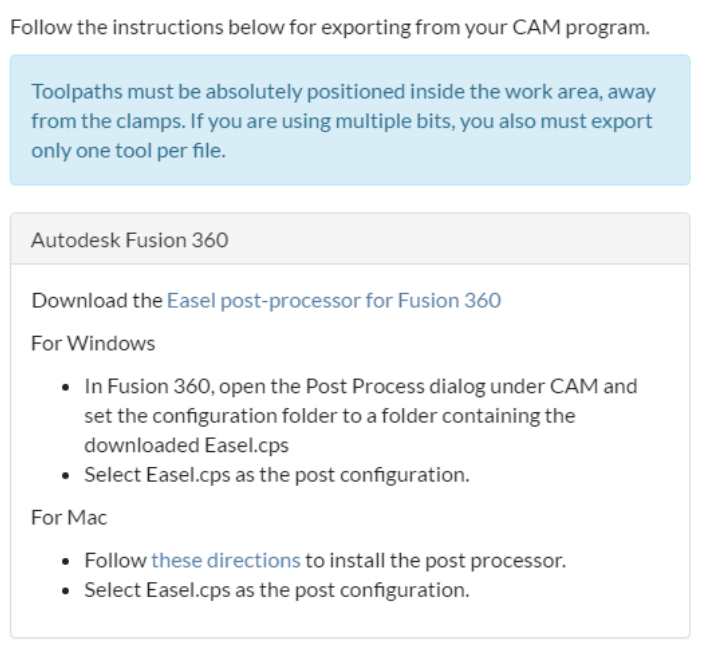
Easel post-processor for Fusion360
After we designed the file, we exported it as a g-code file into FlashCutCNC4.

FlashCutCNC4
We realized our X-axis was off by around 1.5 inches, but instead of altering the code we just jogged our CNC spindle to a different start point. We then realized our step values were too small and one side would take 4 hours to cut minimum. We stopped the program and went back into the Easel plugin and adjusted the cut style to adaptive cutting instead of pocket cutting which allowed us to take big bites with the bit at deep areas and cut less in smaller areas. We decided to take about half inch bites and the deepest.
Final g-codes in .txt files:
When adaptive cutting, we had some problems with the size of the wax piece we used. It was too big so the spindle got caught when it tried to cut the second depth. To solve this, Professor Wettergreen stopped the spindle and used a utility knife to snap off the pieces of wax that would interfere with the tool path. The first iteration was created using a 1/8 inch flat-headed bit and we had issues with the smoothness of the cut.

High wax sides that hit the spindle
Furthermore, the start RPM of our cut was around 30,000 RMP which was far too high and caused our wax to melt around the area which also left bumpy chunks around the top of our bottom piece. Joe changed the RPM to around 10,000 at a 120mm feed rate and the cut went much smoother as the wax came off instead of sticking to the bit head.

Wax after rpm had been lowered to 10k rpm.
We also noticed that the pegs were a bit too close to our design on our bottom piece since the bit was unable to cut all the way in between the peg and the design. We fixed this after the piece had been cut by scraping out the area with a utility knife. We also cleaned up the edges using a bandsaw and scraped off some chunks of wax from the top side using a utility knife.
For our second try, we changed out our wax piece for a smaller cut piece (73mm x 58mm x 40mm) so we wouldn’t have the problems with the walls. We also changed the bit head for a 1/8 inch ball end bit in hopes of getting smoother edges. Our second try was far more successful (although we still had to jog the x-axis a bit left in order to start in the right area). It was smoother and also had no issues with the spindle hitting walls. We still had to adjust the pegs since the bit wasn’t able to reach that area in between.

Flat head bit with high rpm settings

Side view of high rpm flat ended mill

Ball Head mill (top) vs Flat Head mill (bottom)

Close up of sides made by flat headed mill (left) and ball headed mill (right)
Next, we surrounded our piece with styrofoam (like we saw Lucas and Brian do) and poured in an mix of Oomoo to create a negative mold. We let it cure for one day and then began making dittos. We realized that we couldn’t use our pour spout since it was too small so we just poured solution into both sides and fused the sides afterwards.

Oomoo molds
For making objects we used SmoothCast 3000 and SmoothCast 325.

Smoothcast 325 bottles
For Smoothcast 3000 we mixed equal amounts of solution A and solution B and then mix for 30 seconds. Then we poured the mix into the molds and let set for around 3 minutes. You can also add dye when mixing. We experimented with different colors and also tried mixing together colors to make two toned shapes. Before the mold completely set, we moved the top portion onto the bottom portion so the two sides would fuse together. Then we let the item sit for 5 minutes before post processing with a dremel to sand smooth edges and remove the spout.
For Smoothcast 325 we did the same as for Smooth cast 3000 but with longer mix times (2 minutes) and a longer setting time (10 minutes). The product of 325 came out a more clear, rubbery texture instead of the opaque plaster texture we got from 3000.

Dye pots used for adding color to molds

Postprocessing the object with a dremel to smooth down sides and remove pour spout

Mold progression from right to left (left being later ones)

Cracks in bonding the two sides together

Misaligned edges to be sanded down

Final products (Progression left to right)
