Introduction
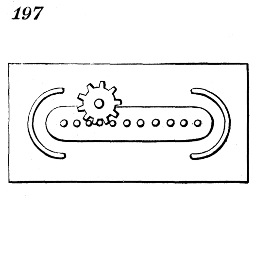
For the second ENGI 210 lab, 2D Drawings, I chose to draw the 197th contraption from the “classical technical reference” Five Hundred and Seven Mechanical Movements by Henry T. Brown, now online at 507movements.com.

The original drawing. (Source: http://507movements.com/img/mm_197.png)
This mechanism is called a “mangle-rack.” From the website:
“A continuous rotation of the pinion will give a reciprocating motion to the square frame. The pinion-shaft must be free to rise and fall, to pass round the guides at the ends of the rack. This motion may be modified as follows:—If the square frame be fixed, and the pinion be fixed upon a shaft made with a universal joint, the end of the shaft will describe a line, similar to that shown in the drawing, around the rack.”
The mechanism’s functionality is best demonstrated with an animated drawing. If the following image is not animated, you can find the animated version at the website.
Drawing Process
- To start, I downloaded the original image from the website to my computer.
- Next, I loaded the image into Adobe Illustrator.
- By tweaking the “Image Trace” options and running the script inside of Illustrator, I was able to get a decent (but unacceptable) vector outline of the original drawing.
- The outer box was trivial to draw using the Line tool.
- The semi-circular “guides” at either end were challenging because I took the wrong approach first. More on that in the Lessons Learned section. To get the final semi-circles, I made a set of Illustrator guides to mark the top, middle, and bottom heightwise, and the left-most, middle, and right-most sides of both guides. I had to do some eyeballing, as the vector drawing was not perfectly equal. However, I made sure that the guides were symmetrical vertically, so that any further work could rely on the guides.
For the left guide, I used a curved line from the top right guide intersection, to the left middle intersection, to the bottom right intersection. I mirrored this vertically for the right side. Then I gave the line a large, rounded stroke and the guides came out nicely.
- The rack outline was trivial to make using the Rectangle tool, and then making the corners rounded.
- The rack teeth were similarly easy to make, using 2 circular ellipses at either end of the rack, and then using the Object Blend tool in Illustrator to repeat the pattern a certain number of times between the two.
- I used geargenerator.com to make the pinion, and had to eyeball it, importing between Illustrator and the website, until the teeth looked like they would move freely.
- The final result:
Lessons Learned
- When making the guides, I originally tried to use curved lines to outline the original drawing. This produced poor, arbitrary lines.
- Object Blend is great because it reduces repetition, and if you need to make changes to your repeated objects, you only need to modify the ends of your Blend.
- By using layers from the start to isolate the original drawing, the work in progress, the guides, and the pinion, it made it very easy to iterate and work efficiently.
- I do not know how to correctly choose gear sizes or teeth sizes/numbers. I will need to do some research to find out if this is feasible with my background.
Download
You can download the final .AI file here: mm_197-1xhs6va.


