For this final project, we were tasked with using CNC machining, molding, and casting to create chess pieces. Each partnership was tasked with creating two of a certain chess piece, and then we would all put them together in the end to form a full chess set. My partner and I chose the knight chess piece, and we began by looking for a piece on Thingiverse. We found a cool-looking dragon-knight chess piece and tried to cut it in half using SolidWorks (Figure 1). However, we realized that we can’t really edit it because it imported as a Graphics Body instead of a Solid Body. When we tried to import it as a Solid Body though, our computers couldn’t handle opening the file because there were over 400,000 facets that it needed to load. Unfortunately, every time we tried to load it, it would freeze or crash. :'(

Figure 1: SolidWorks Knight/Dragon Graphics Body File
We then looked at previous ENGI 210 blogs for help, and we realized that we don’t even need to use SolidWorks. The Ditto blog was super helpful because of how detailed it was.
We used the AutoDesk MeshMixer to reduce the number of triangles that our file had. I reduced to 10,000 triangles, since it had a lot of facets when we tried to import it in SolidWorks (Figure 2).
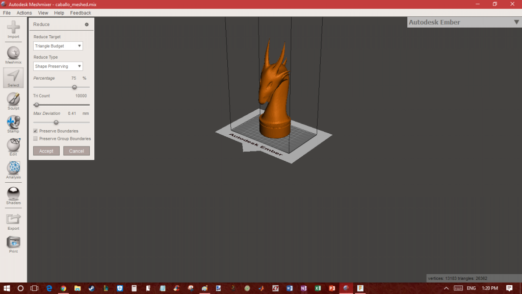
Figure 2: Meshmixer Knight Dragon Chess Piece Reduce Traingles
Next, we imported it to Autodesk Fusion360 and planned to add boxes to the piece so that we would have a left half and a right half. However, we realized that the dragon piece was way too complex for our laptops to handle and that the CNC machine wouldn’t be able to cut out the area between the horns.

Figure 3: Meshmixer Reducing Triangles of Horse Chess Piece
Sadly, we decided to not do the dragon and chose another knight piece instead. We really liked the knight piece shown in Figure 3, so we went ahead and used that one. It took quite a while to figure out how to use Fusion 360 to add the boxes, cut out the pegs, generate the toolpath, and obtain the gcode, but after so many long hours, we finally got it (Figure 4).
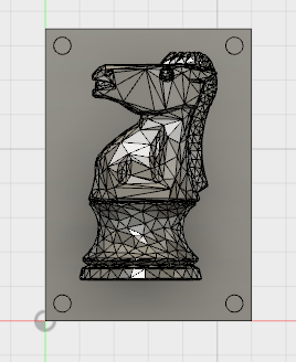
Figure 4: Autodesk Fusion360 Knight Horse Chess Piece Side with Pegs
Afterwards, we went on to the CNC machine and used the FlashCut program to attempt to CNC our wood block. However, this process took so many hours as well to actually get to work.
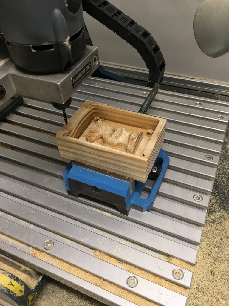
Figure 5: CNC Machine Cutting Out One Side of Our Chess Piece Block
It took us a long time to realize, but we actually had to take out the lines of code with M and G54 since they were giving us errors. After doing that, the CNCing went fairly well. We had to try several times to get the zero in the correct place because the wood block was so small.
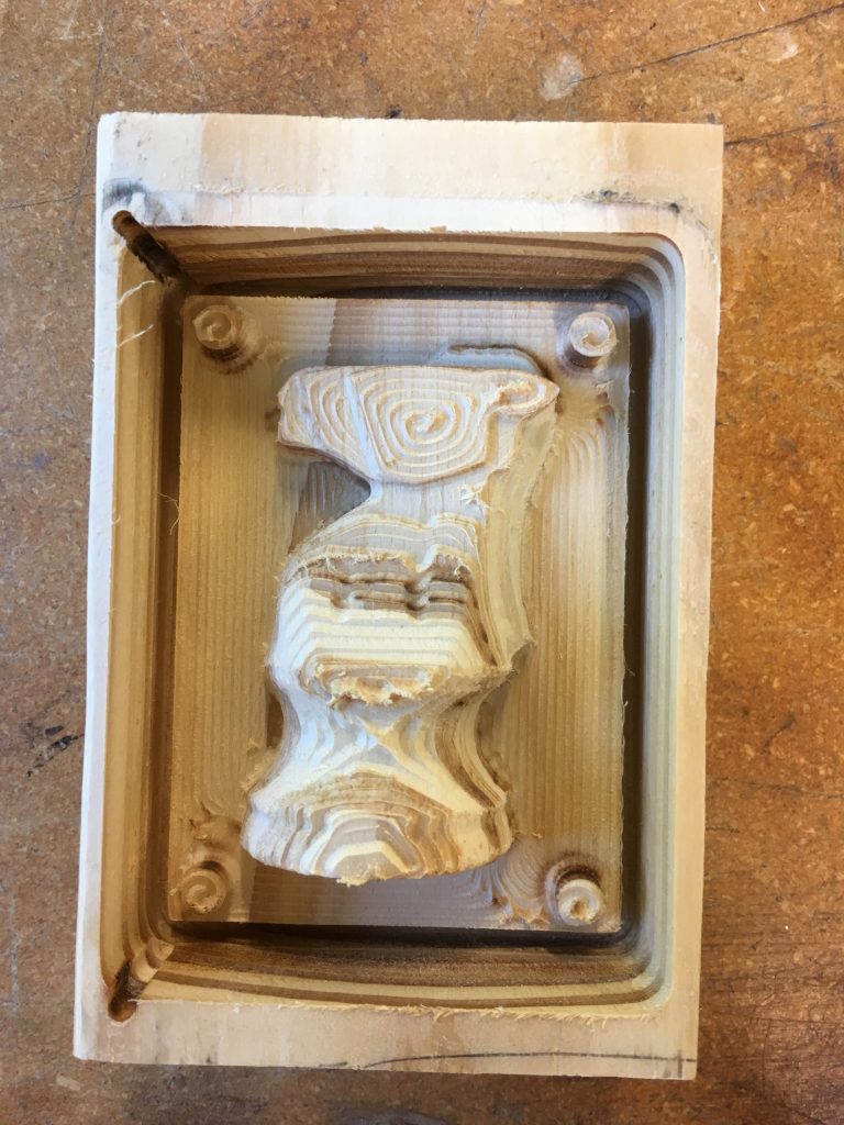
Figure 6: After CNC Wood Block with Knight Chess Piece
It was almost the exact size of our piece which is not preferable because that meant that we had to get the zero in the exact correct place.
In the end, we got both blocks (Figures 5-7). Unfortunately, we didn’t realize until we were about to create the mold that the pegs weren’t cut out onto one of the blocks. That meant that we wouldn’t be able to line it up exactly, but we decided to just continue with it and hope that we could get it to line up well enough.
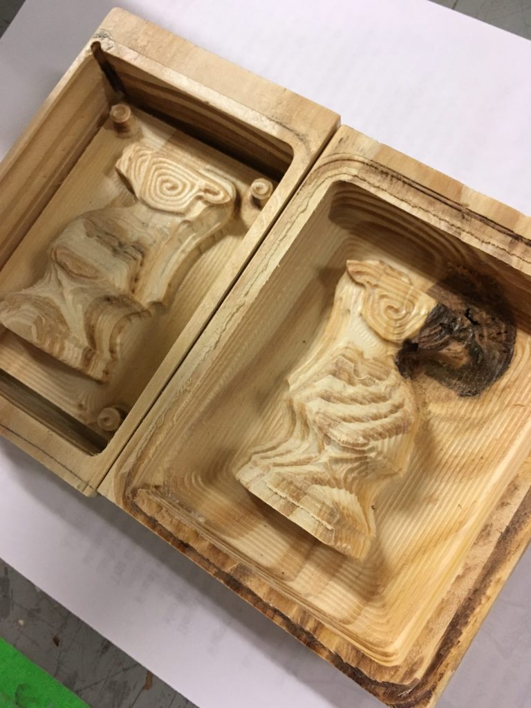
Figure 7: Both Sides of the CNC Knight Chess Piece Cut Out of Wood Blocks
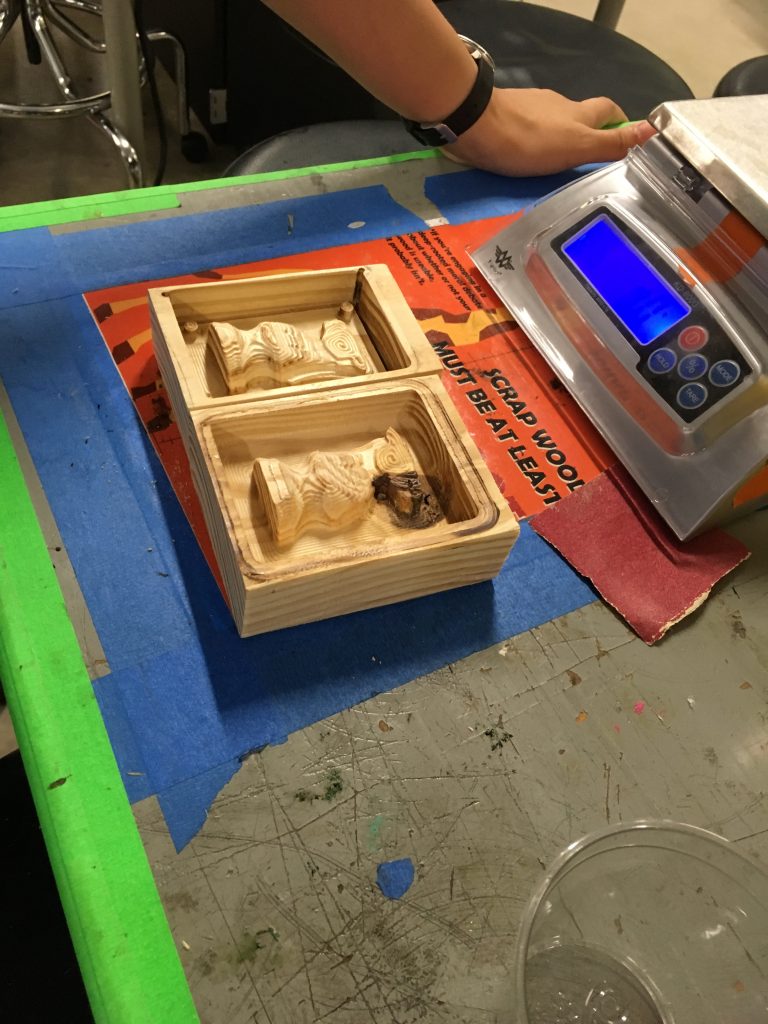
Figure 8: Weighing Out the Mold Star Part A and B
We weighed out and poured in the Mold Star Part A and B into the wood blocks (Figures 8-10) and then waited over 24 hours for it to cure.
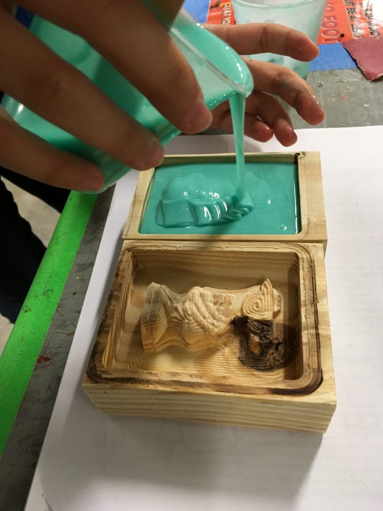
Figure 9: Pouring in the Mold Star into the Wood Blocks
When we went to take it out, we had a lot of difficulty taking out the mold from the wood block with the pegs because it also had a deeper outer layer around the horse. We ended up having to break off sides of the wood in order to get the mold out (Figure 11). Afterwards, we cut out the pour spout for the mold and then proceeded to make the pieces (Figure 12).
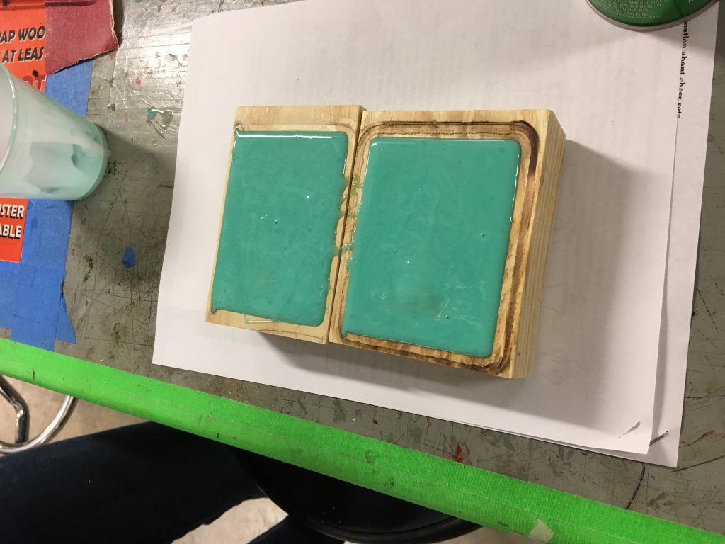
Figure 10: Waiting for the Mold Star to Cure in the Wood Blocks
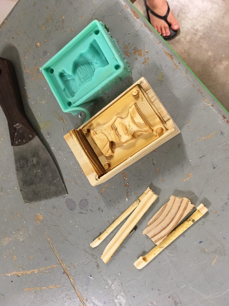
Figure 11: Breaking Off Sides of the Wood Block in Order to Take Out the Mold
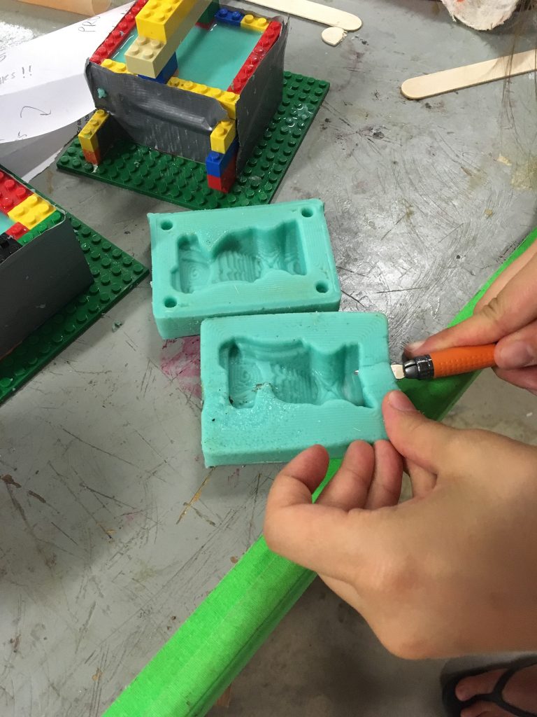
Figure 12: Cutting Out the Pour Spout for the Mold
We had trouble getting the sides to stay aligned, so we had to try several times. Also, when we made the black piece, it turned gray for some reason. We decided to just sand both pieces down and then spray pain the gray piece black (Figures 13-14). In the end, the pieces turned out fine even despite all of the troubles we had (Figure 15). I’ve learned a lot about how things can go wrong or not turn out as expected so easily, and this project has been a really good lesson in bouncing back from those set backs and figuring out new ways of solving the problem. All in all, I really enjoyed this class and all of the stuff that we learned, and I’ll definitely keep and use all of this prototyping and fabrication knowledge in the future.
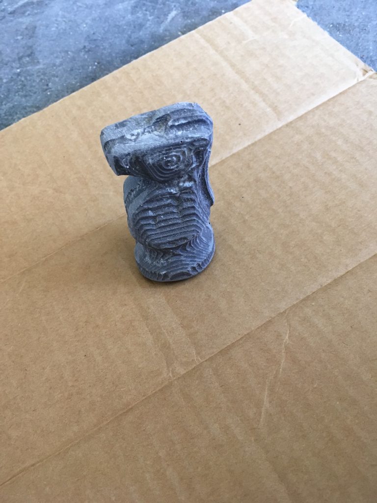
Figure 13: Gray Knight Chess Piece Before Spray Painting

Figure 14: Gray Knight Chess Piece After Spray Painting
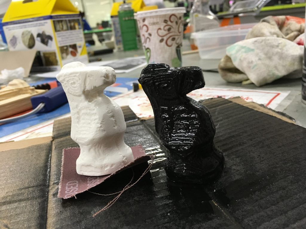
Figure 15: Finished White and Black Knight Chess Pieces
