For our midterm, we were instructed to build a model of a mechanical movement. It sounds simple right? Nope. If I can only take one thing away from this class, it would be that nothing is as simple as it seems.
The first thing I did after getting this assignment was talking to people who have already done this assignment and seeing if they have any advice. I learned that I should grease my wheels and NOT PROCRASTINATE on this assignment. Knowing this, I started fairly early.
My first step was redoing my mechanical movement. I decided to change my movement to #118 and after googling a little, I found a youtube video of an assembled design that I modeled mine off of.
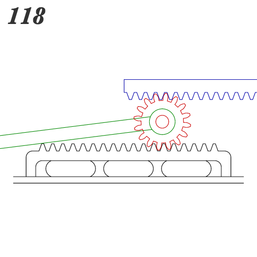
I knew my gears from my first 2D drawing will not mesh, so instead of using illustrator to trace gears again, I scoured the internet for a rack and pinion generator and, thankfully, I found one. http://hessmer.org/gears/InvoluteSpurGearBuilder.html
After getting my gears, I imported the .dxf file into SolidWorks because it is so much easier to dimension things. In there, I made them the size I wanted by extending the racks. Then, I imported the rack and pinion back into illustrator because I couldn’t figure out how to mate things correctly in SolidWorks. After making the rack and pinion, I needed the 3 long plates that would spin the gears and the stand it will stand on. I used shapemaker to make those. Finally, I needed a stand to place all these parts on.
After making all these parts, it was time to cut. I first cut out the pieces on cardboard just to see if everything meshed properly, and it did. But, I realized that I needed a back piece for the gears to rest on and to restrict movement to only left and right. I designed that by adding slots to a rectangle just large enough so that the dowels can slide back and forth on.
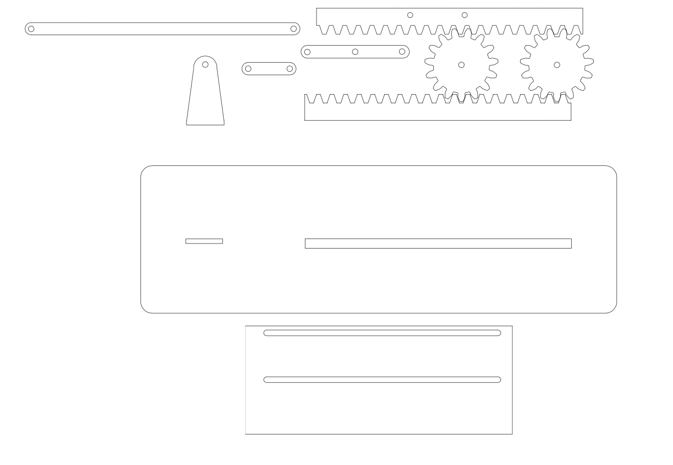
All the pieces minus the dowel caps
The next step was to scale up and cut on wood. When I cut everything out on wood, I realized that the dowels slid right through the holes I made, so my temporary solution was to stick tape on them as “caps” so they didn’t slide out. From that, I knew that I needed dowel caps to press fit on the outside so the gears stayed in place. I did that by measuring how big the dowels actually were and subtracting 0.02 in off of that. I also needed a way to keep the top rack in place so I added another slot to the back piece of wood and added two holes to the rack so I can press fit dowels into. Another issue I ran into was cutting the dowels. I tried using the PVC cutters downstairs but I had a hard time cutting through it without squeezing the wood too much. I also tried the hand saw downstairs but it took forever to cut through the 1/4″ dowel and split my wood too much. At that point, I was slightly lost so I asked around a little and Cole told me to use the band saw. It was a good idea but as I was about to use it, Joe handed me a better hand saw and that worked fine so I stuck with that.
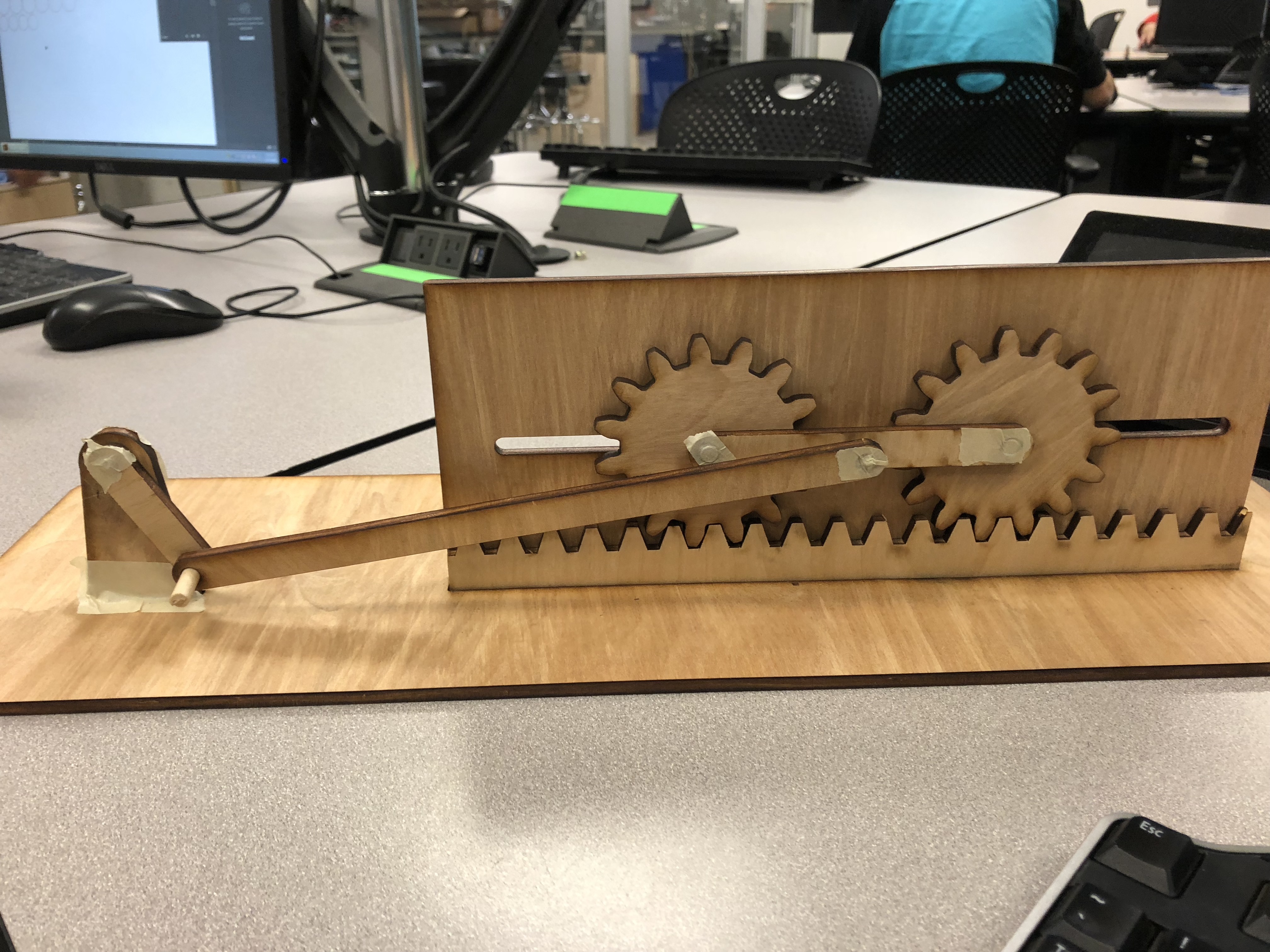
Medium Fidelity Prototype with missing dowel caps
So after figuring out my dowel caps and cutting dowels issue, I decided to get a little creative. I wanted to add the Rice Owls to the other side of my design so that they would spin. It seemed like a great concept but when I tried to put it to action, I realized that my mechanism wouldn’t be able to spin all the way, so I scrapped that and went back to my original design.
After cutting all of the pieces again, I stained it with the mahogany stain. The stain really transformed my wood and made the whole design have a rustic vibe, which I really liked.
For the plasma cut pieces, I decided to make the 3 flat plates. Per suggestion from Dr. Wettergreen, I didn’t plasma cut the holes. Instead, I just plasma cut the plates, printed the outline, taped that to the metal plates, and then used the drill press to drill the 1/4″ holes. It worked really well, definitely better than if I were to use the plasma cutter to cut the holes because I know that it would have been really imprecise. To post process the pieces, I used an angle grinder to get off all the slack, the wire brush sander to smooth out the edges, and the *new* sand blaster to get a matte and smooth finish.
Finally, after all this, it was time to assemble. The hardest part of the assembly was getting all the dowel caps on. It took a lot of hammering with a mallet and frustration, but I eventually got them all on. I used some tallow to grease the gears and it made them run a lot smoother.
At this point, I noticed that the structure was kind of wobbly and Wettergreen asked why I only used one layer of wood, and it didn’t even cross my mind to use more than one. He suggested that I add some supports to the back so that the pieces sticking up don’t move back and forth. I was going to do this, but after adding some wood glue to the slots on the bottom and letting it dry, I noticed that the pieces didn’t wobble anymore. He also suggested to add another layer to the bottom of the whole thing to make it more sturdy. I did do this, and it did make it feel more secure.
THE FINAL RESULT: IMG_6689-wmy4uy
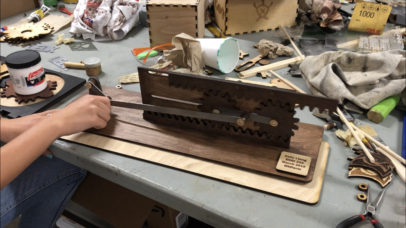
I really like the contrast between the unstained wood and the stained wood. I think that the unstained dowel caps and the name plate look really good against the dark wood.
From this project, I realized that the sun can set and you wouldn’t know because the OEDK has so little windows. I also learned the importance of starting early so that you have time to fix your mistakes. Also, the drill press downstairs is backwards and really confusing and really easy to hit your head on.
