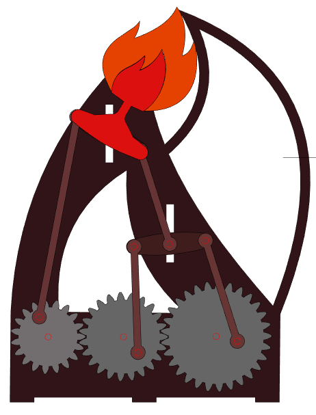
For the midterm project, we were assigned with creating a working mechanical model inspired by one of the 507 Mechanical Movements. A lot of people in the class used the same movement that they had made from the 2D drawing assignment for their midterm project. I thought about it, but really it came down to the fact that the one I chose initially was pretty lame. So byeeee, I picked a new one. The process of picking a new one basically consisted of Cole and I browsing through the 507 mechanical movements website and looking for the craziest (least lame) movements. When we came across movement 125, we knew. Movement 125 shall henceforth be referred to as “Crazy Gears”.
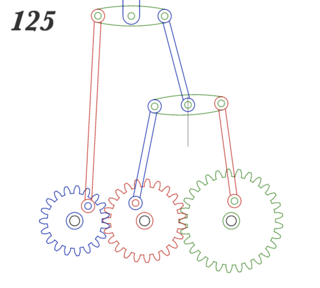
Movement 125 in all its glory
First, I created a 2D drawing of the model. To do so, I broke it down into parts. To draw the gears, I used gear generator. This was especially helpful given I had to fit 3 different gears together and all I had to do was count the number of teeth on the gear in the drawing from the website and specify a few other measurements and it gave me 3 beautiful gears that I could import to illustrator. The other parts of the drawing involved a lot of tracing and aligning circle centers.
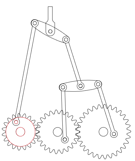
2D Illustrator Drawing
After drawing, it was time to get to actually testing out the design with low fidelity materials. For this model, I exploded all the pieces from the drawing and laser cut each from wood. I ended up with the necessary pieces for the movement, but quickly realized that there was A LOT more needed than just what was on the 507 mechanical movements website. That is, I needed slots for the vertical movement parts to slide in, a place for the gears to connect to, and a way to connect all of the pieces together. From this information, I made a plan: I needed a backplate to which the gears could be connected and the slots could be cut out of, I needed pins and endcaps and spacers to hold all the pieces together, and I needed a base plate so the movement could eventually stand up on its own.
As I was planning out the pins and endcaps and spacers, I realized that my model was very multilayered. There was a large potential for two parts of the design being in the same plane and getting in the way of each others movement. To prevent unwanted collisions and jams, I sketched a side view of the model that broke down all the layers. This aided me in keeping similar parts on the same plane, determining how long the different pins needed to be, determining how many end caps and spacers I needed, and it especially helped later on in assembly of all of the parts.
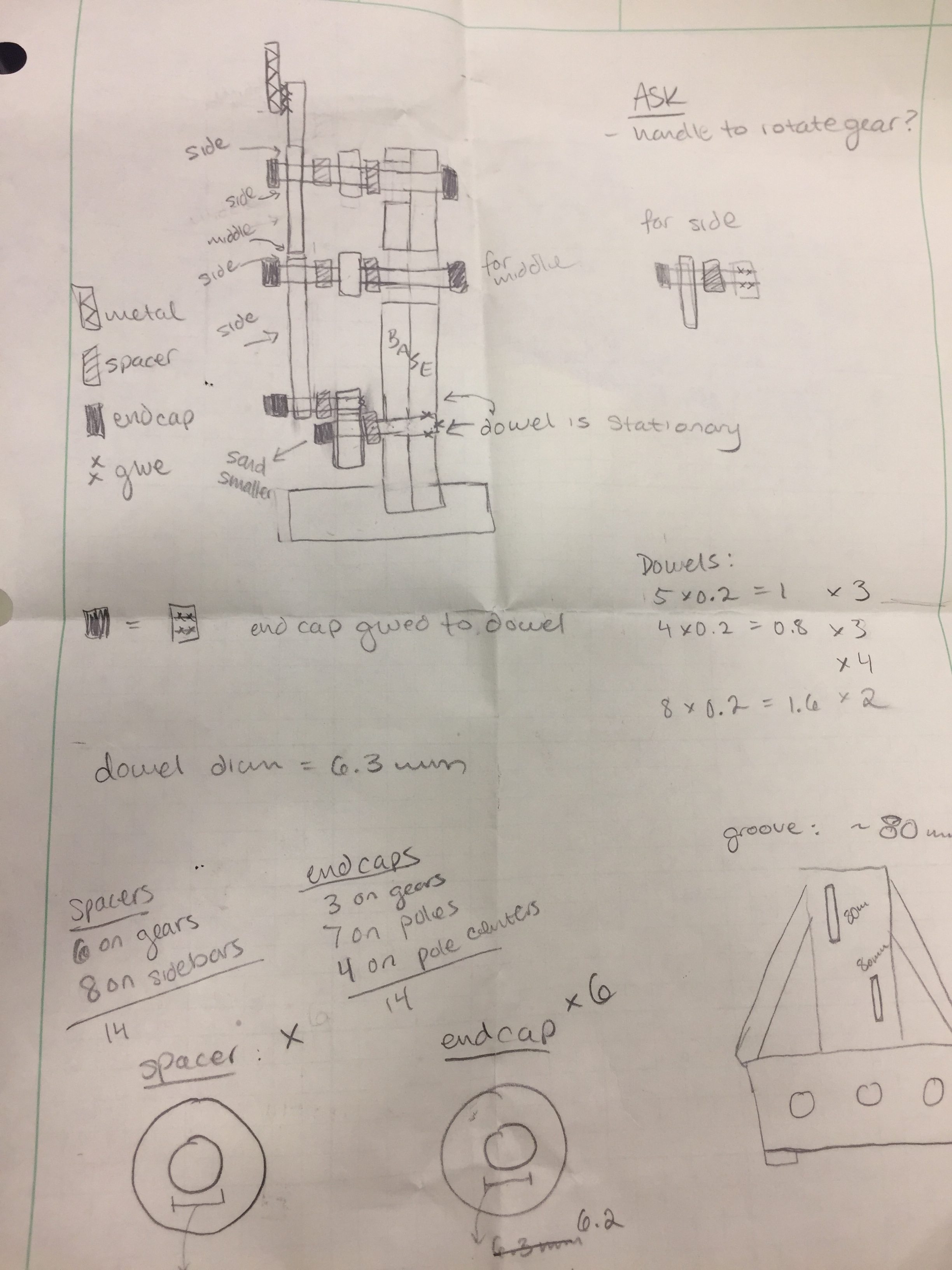
Layering and planning!
After planning all this out, I modified the drawings that I had originally created. I drew a backplate design, created two different size rings to be spacers (wider inner diameter) and end caps (smaller inner diameter, intended to be press fit). I cut out the new parts using the laser cutter and got to assembling this model. I forgot to take a picture of this iteration all assembled, but here’s a picture of the backplate. Just imagine the other pieces assembled on top.
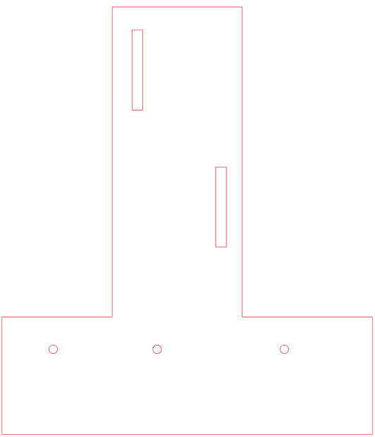
Old Back Plate Design
Here’s a list of what I learned/needed to change after having created this first prototype. Some highlights including changing dimensions to make snap fits tighter, adjusting the dimensions of the slots in the backplate, creating a baseplate with teeth to connect to the backplate, figuring out how to connect my plasma cut piece to the wood (figuring out what even my plasma cut piece would be??), and creating a cooler (less lame) back plate shape.
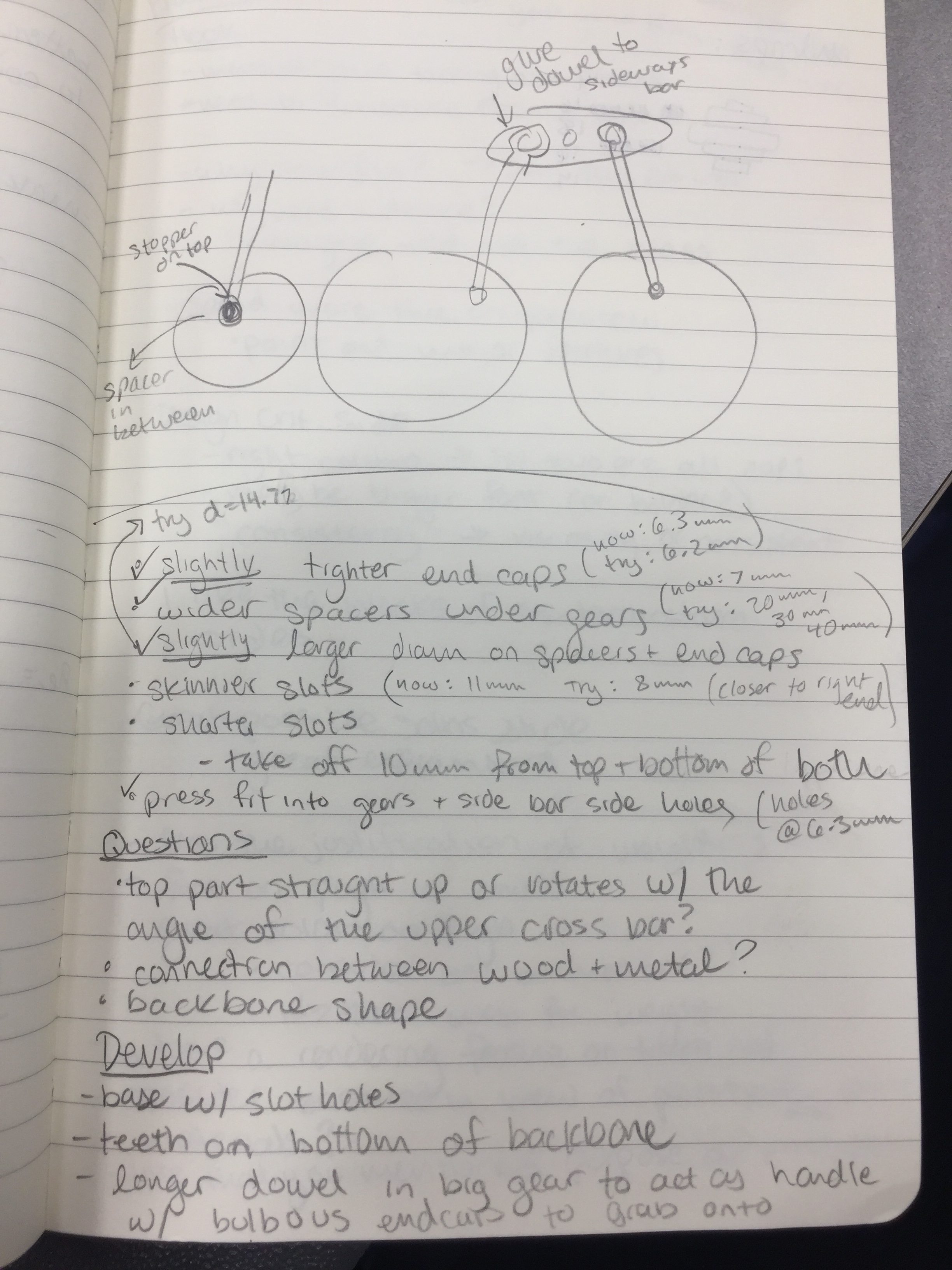
Notes on first prototype
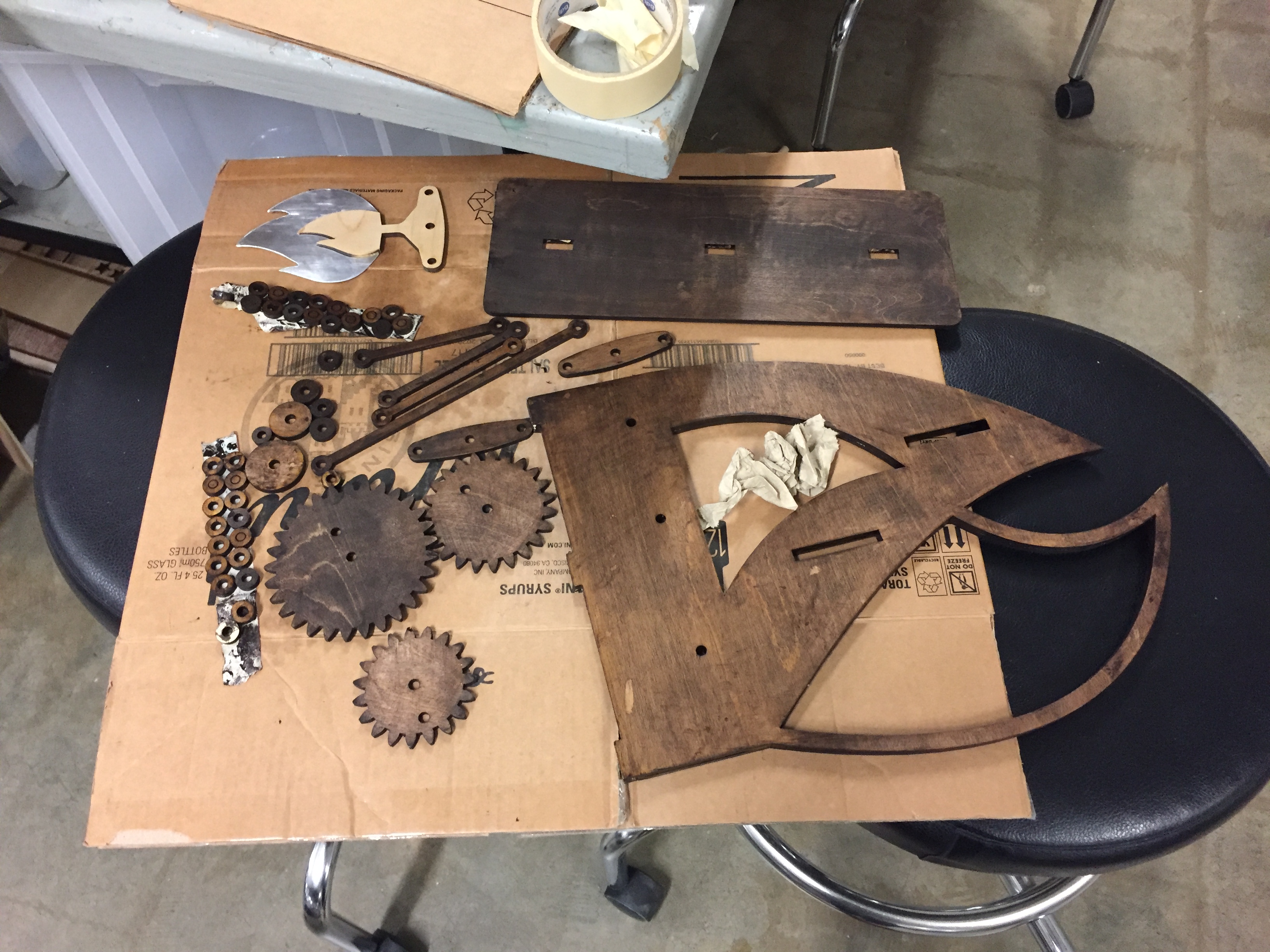
I slowly but surely made all of these changes. Somehow, I decided to go with a fire theme? Not even sure where that came from. But anyways, this inspired the shape of my new backplate (designed in solidworks) and the shape of my plasma cut piece. For the plasma cut piece, I decided to make it more integrated with the model rather than just gluing it on. I chose a fire design with an “inside” and “outside” so the wooden piece could be the inside and also connected to the model itself, and the outside piece could be plasma cut. I was concerned about the weight of the piece so I used thin aluminum for this part.
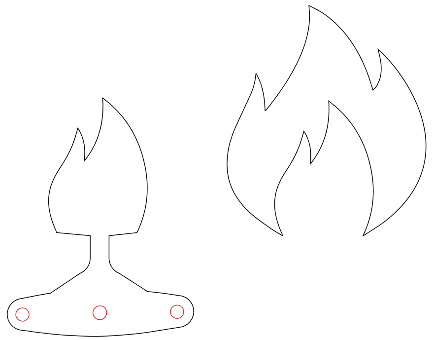
Wooden flame (left) and metal flame (right)
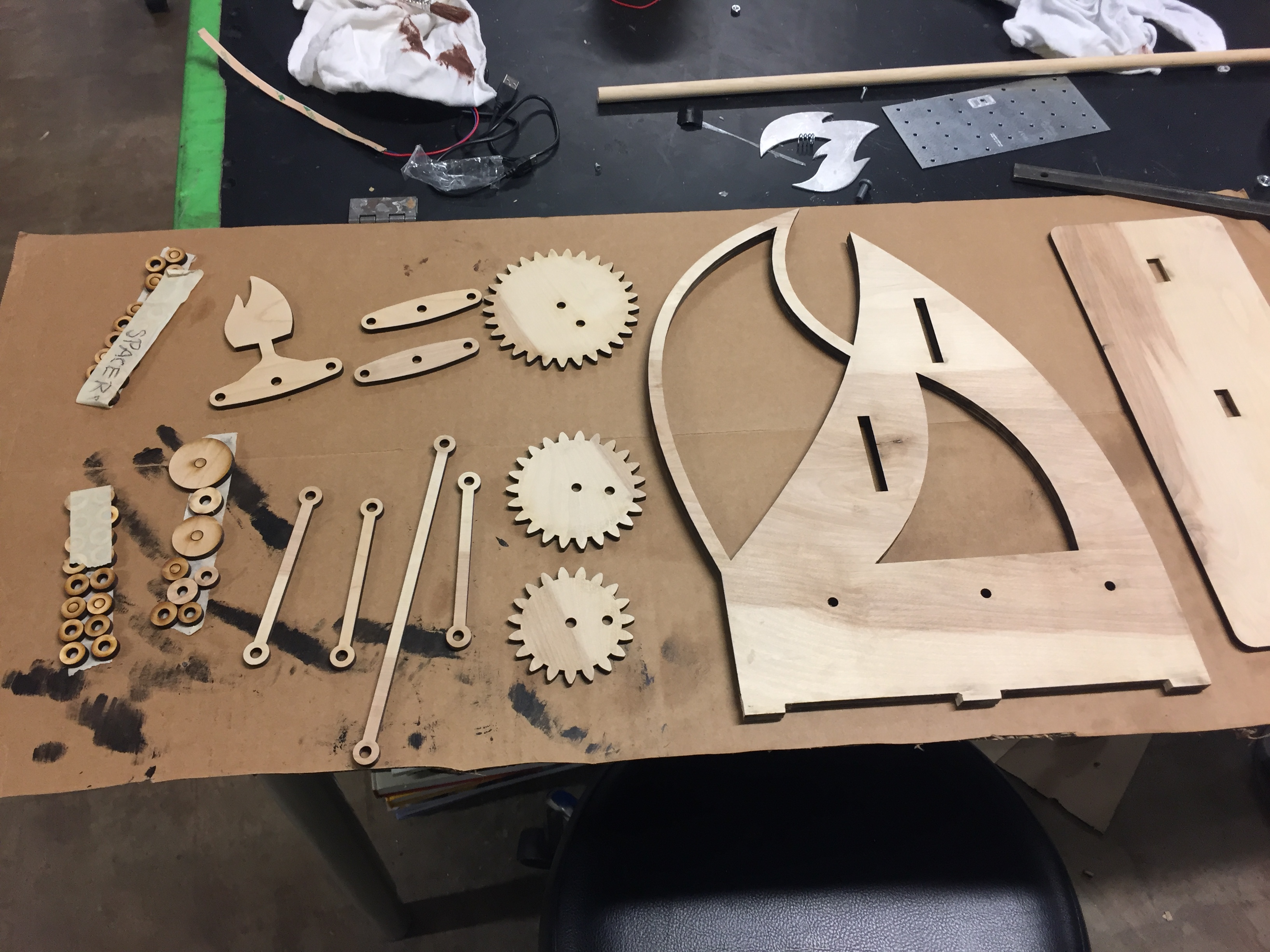
Ready to be assembled! Flame-inspired back plate on the right
After I made all the changes, I quickly assembled the pieces to check for function. It worked pretty well! However, a few issues arose with the caps on the dowels that served as axels for the gears — they were just slightly too tall, causing the long bars connected to the perimeter of the gear to collide, thereby causing the mechanism to jam. To remedy this, I decided to sand down the dowels/endcaps, however I ended up having to repeat this touch-up after post processing and assembling a second time.
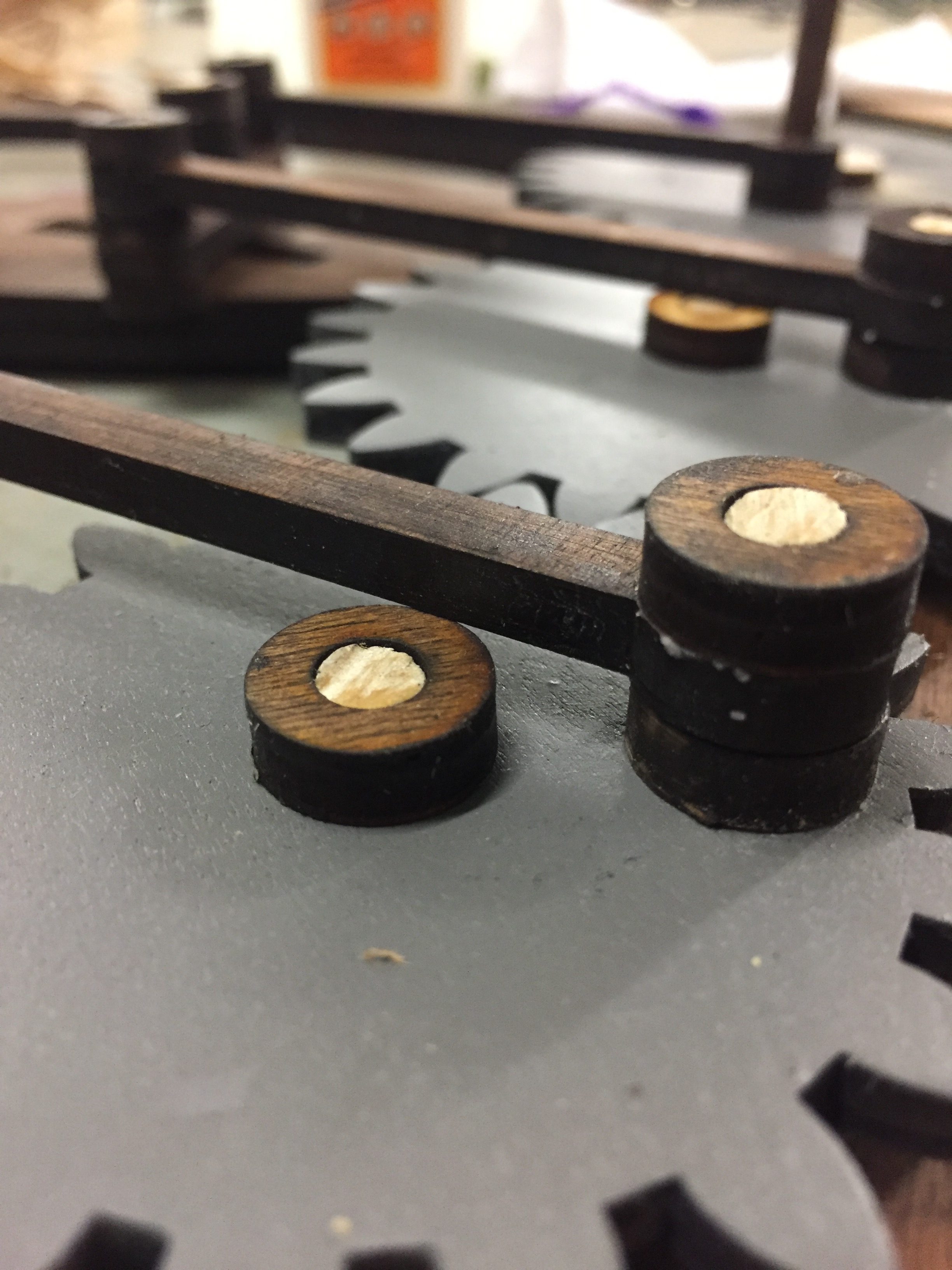
The end cap just barely blocks the bar from passing over
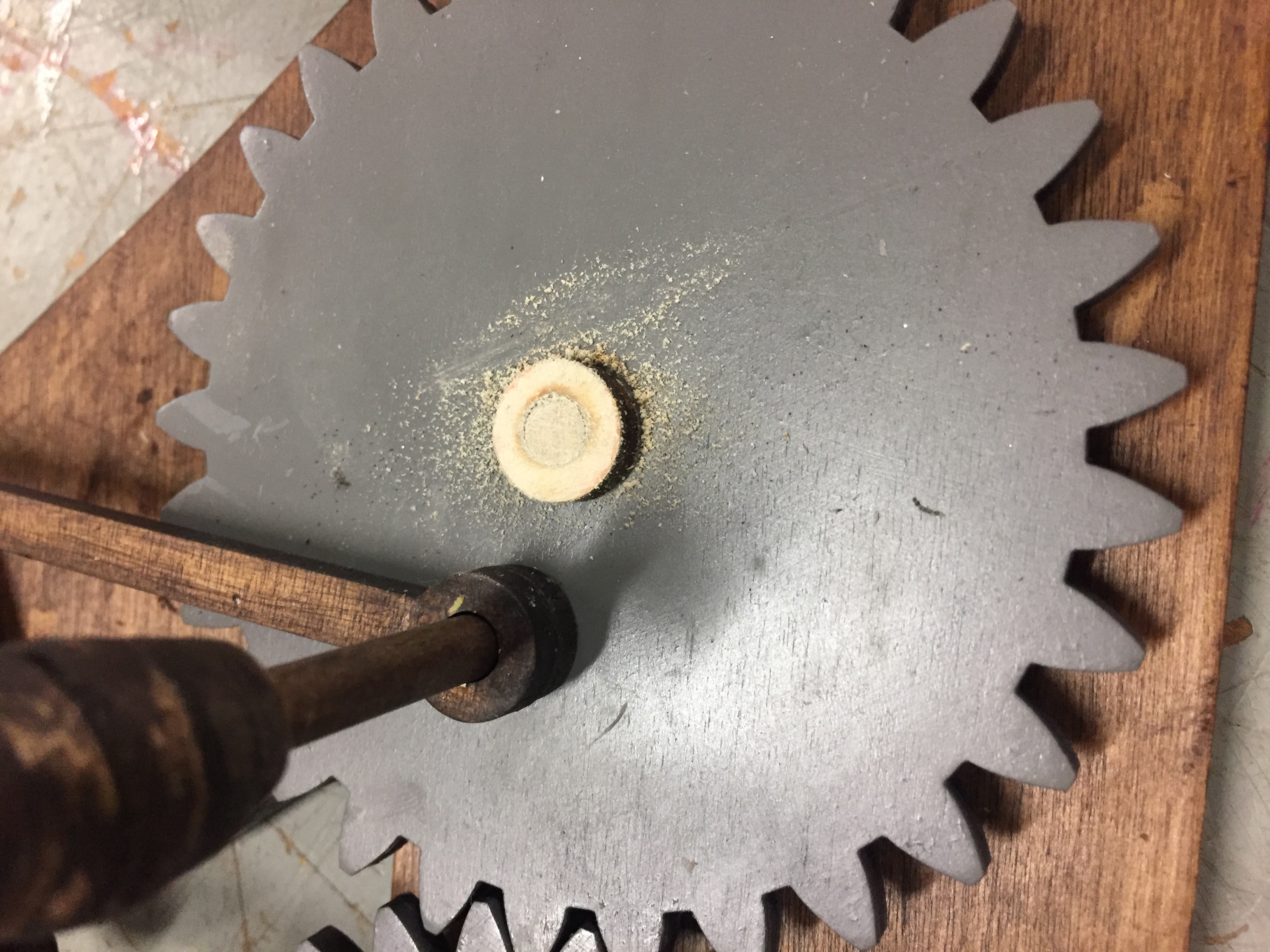
Sanding down endcaps to avoid rubbing and contact
Next, I jumped into the post processing stage (as previewed above). First, I angle grinded and sanded my plasma cut piece. I painted the wooden inside of the flame with red spraypaint and the metal outside of the flame with “flame orange” spray paint, then press-fit the wooden and metal parts together. I stained the wooden pieces a dark coffee stain, spray painted the gears gray. I wanted to make the background dark so the fire color would pop, and I wanted the gears to look somewhat mechanical or industrial. To make the handle more ergonomic, I stacked different sized donut pieces of wood on a dowel and used the belt sander to smooth it into a bulb shape.
AI Drawing with color
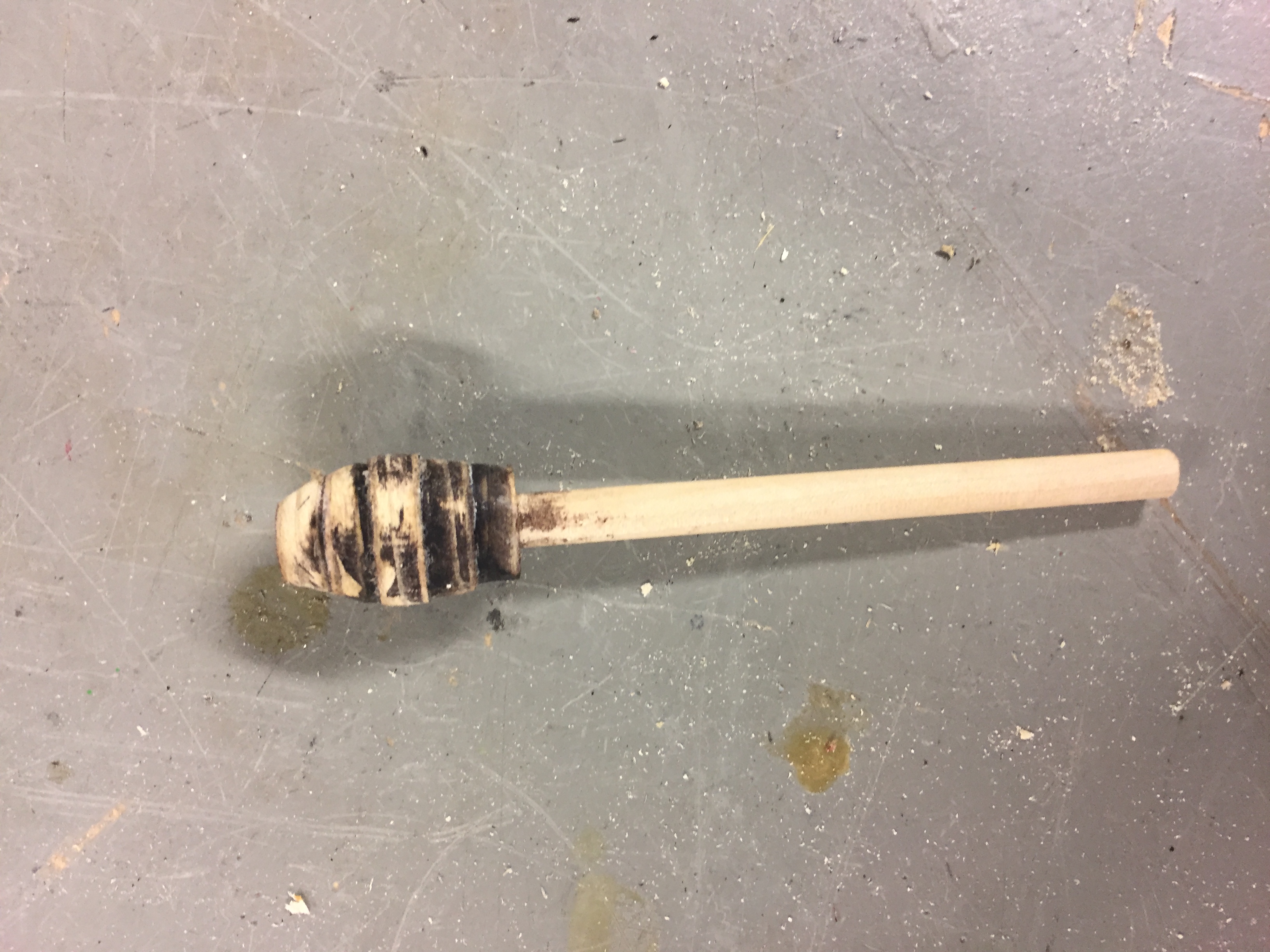
The smoothed out handle
stainz for dayz
In terms of assembly, I had done it enough times at this point to know where pieces needed to be sanded down and where lubrication was needed. I had certain difficulties gluing in the dowels to surfaces or end caps and not letting the glue ooze out and affect the surrounding pieces which were to be free moving. As mentioned above, I also had difficulty ensuring that the bars did not run into the end caps. One issue that arose was the fire piece running into the backplate (because its just so crazy). Theoretically, based on the layering system this shouldn’t happen. But it did happen so I did my best to remedy this by pressing the press-fit end caps on tighter and trying to seal them in place using glue. This did the trick, but I’m worried it will not be a durable solution.
There are two minor unsolved problems with the model. First, the thickness of the handle to turn the gears is too small, which ends up applying a torque rather than having the entire handle/gear element act as one rigid piece. This could have been fixed using a larger dowel, however the end of the handle actually serves to move one of the vertical bars as well so that piece would have had to be modified in addition. For now, the model functions better when the user spins the gear itself, but is still operable with the handle. The second issue is a missing endcap on the rightmost gear/bar interface. This allows for the bar to move forward along the dowel as the gear is turned. It was too late to go back and put some sort of stopper at an intermediary position on the dowel, but I will look into fitting something on to it before I leave for spring break to ensure that it is a sturdy fit. Overall, however, if I’m being honest, the final product came out pretty ~fire~.
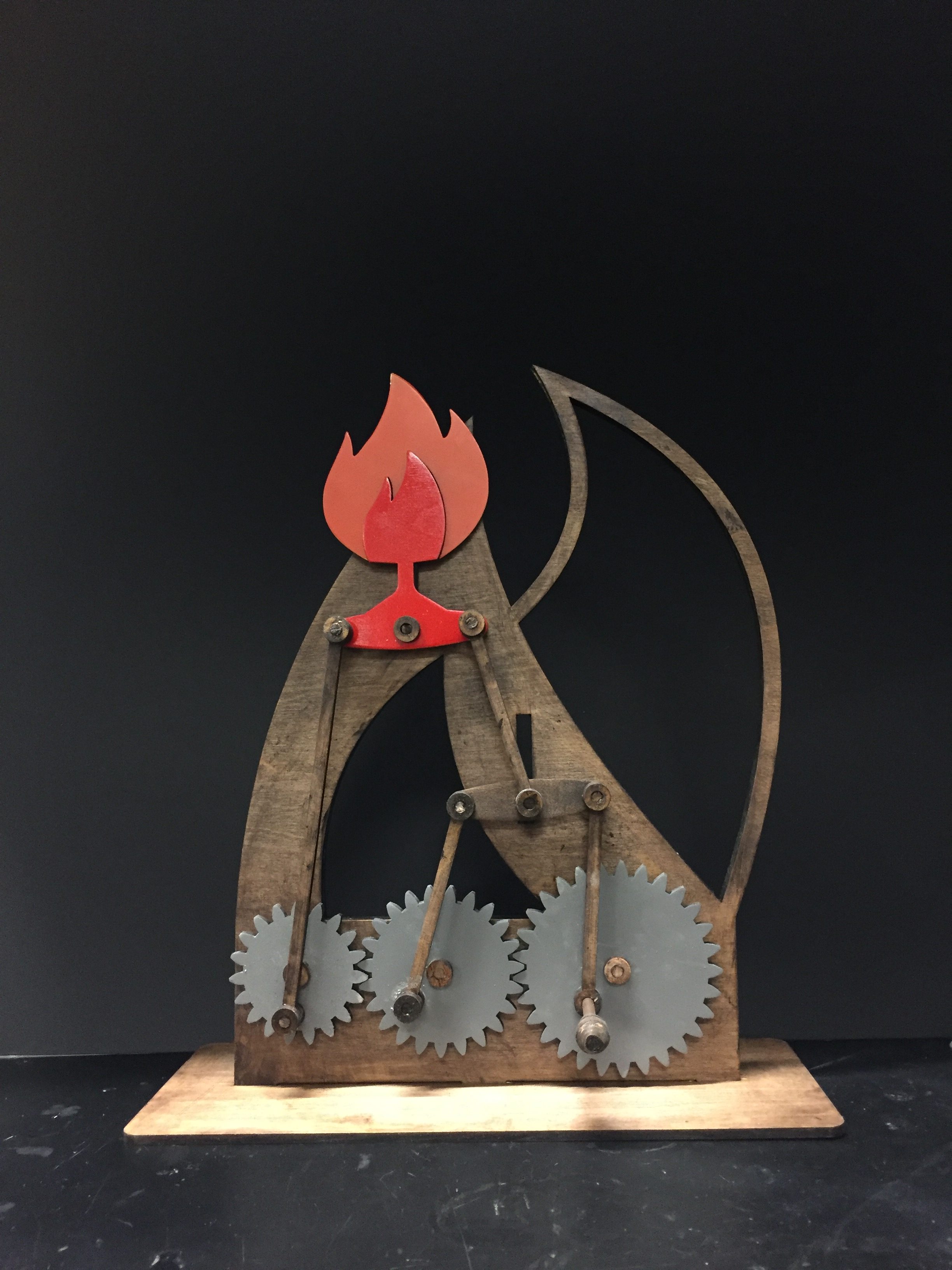
It’s LIT
Overall, I am very happy with the outcome of this project. I really enjoyed having the autonomy to design my own model completely and learn along the way.
