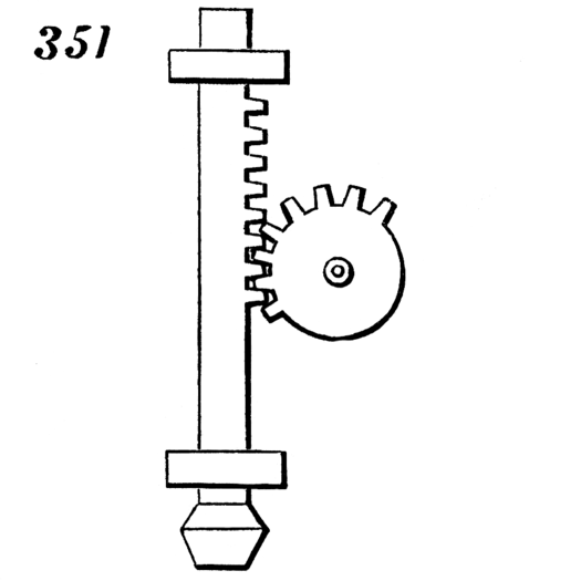
 The movement I selected uses a mutilated toothed gear to drive a toothed rack guided by rings on either side of the toothed region. The gear rotates clockwise and pushes the rack upward until the teeth no longer mesh and the rod falls straight down. The rod would be stopped when the head contacts a surface (which would be below the image shown). The gear continues rotating clockwise until the teeth mesh and the cycle repeats.
For ease of manufacturing, I decided to remove the stamping head at the base of the rack so that the guide rings can be easily slid around the rack during assembly. Note that the placement of the guide rings and the gear’s crank shaft do not have a base object to attach to in this drawing or in my file. This is to allow the part to be attached at any surface that it is desired, however, it is essential to consider the proper spacing between the gear’s center relative to the rod’s translational axis AND that the teeth of the gear correspond properly to the teeth in the rod.

 My drawing is intended for the gear’s center to be 1.05″ radially distant from the rod (red) and aligned with the midpoint between the guide rings (blue).
Another major consideration was the thickness of the material which will be cut. The size of the guide rings are directly defined by the thickness of the material, in addition, the angles at which the gears mesh is also designed around the material properties of the gear and the rod.
![]()
My design is intended to be cut on 0.20″ thick aluminum with tool paths offset such that the true shape of the drawing matches the true shape of the manufactured parts. I would recommend manufacturing this on a waterjet for a high-precision cut.
To create the file, I began with the rack. I made it 5.00″ long by 0.30″ wide with teeth protruding on one of the long sides. The teeth are repeats of the same tooth path which I defined using straight lines for the tooth addendums/dedendums and Bézier curves for the tooth faces. Generating the teeth was the most challenging part of this assignment because there are not free gear generators for rack and pinion systems (nor for mutilated gears). The rack has a total of 8 gears which span a distance of 1.9 inches. This distance was selected with respect to the 5-inch total height to keep the teeth from ever contacting the guides during the cycle.
 The guide rings were made rather simply. The inner hole is defined by the material thickness and the width of the rack (0.20″x0.30″). I decided to make the outer rectangle 0.30″x0.40″ to give the part 0.10″ thickness.

Lastly, I made the gear by copying the same tooth profile as the rod and copying it in a circular pattern 8 times at fixed rotational angles about the center of the gear. I then completed the gear by defining the dedendum circle and removing the paths which separated the teeth from the rest of the gear’s body. At this point, I began the iterating the tooth geometries in order to mesh the gear with the rack at an appropriate contact angle while maintaining a system which does not choke or have significant fall-back between teeth. The most difficult part of the tooth design was maintaining an appropriate negative space between the meshed teeth of the gear and the rack in order to prevent the system from jamming. I achieved this by visually copying the geometry of example teeth on geargenerator.com. There are still a few issues with fall-back pertaining to the linearization of the gear-pattern on the rack, but I do not have the knowledge to effectively address this issue. For situations requiring a more precise mechanism, one could consider using a 3D CAD packages which has stored rack and pinion profile generators and then import the drawing file into illustrator for scaling and fabrication.
The .ai file can be accessed here: Mvt. 351 Rack and Pinion, and remember to offset the tool path!
Evaluating the cost:
- Design Cost
- The file took me approximately 5.5 hours to prepare such that the gears visually mesh.
- I would charge $8/hr due to my lack of proficiency in the software.
- There is not an online rack generator, which makes this file more customized and therefore more valuable.
- Access to Fondren Library for a Rice Alumnus is $75/year. Fondren Library has computers with the most up-to-date Adobe Creative Cloud Software.
- I would argue that this assignment would constitute 1/52 of the Fondren Library cost as the file creation a period of one week for me.
- Consumable Cost
- 12″x12″x0.20″ aluminum sheet = $30
- We could make 6-8 of these mechanisms with a sheet of this size
- 12″x12″x0.20″ aluminum sheet = $30
- Machine Time
- Estimated 45 minutes for file processing and water jet machine time
Total Expense: $74
