Introduction
The main inspiration for this project came from a mobile video game called Monument Valley. The game involves a series of platforms and stairs that players need to rearrange in order to move their character along and reach a designated goal. Attached is a video taken directly from the video game of the movement and map that we intended on creating.
what we planned
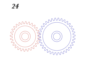
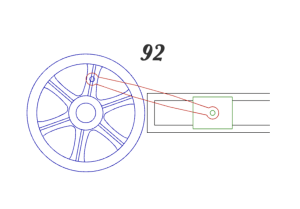
After researching different mechanical movements, we were deciding between a cam/follower mechanism that could push the stairs up and then have them fall or having a gear train that could achieve randomized movements of the stairs. In order to do this though, we needed to come up with gear ratios that could achieve different rotational speeds. Austin performed a set of linear equations to find the right gear ratios and after tinkering with the Gear Generator website, we decided to do a 7-gear train combined with linear actuators to accomplish this movement. Although it was a very ambitious task, we wanted to try our best to create the randomized motion seen in the video game. The mechanisms we planned to achieve were #24 and #92.
Once we created the gears, we realized that the stairs would have to be very large in order to house the rotational actuators. On one hand, we figured that scaling upwards could be beneficial as it would give us some room for error in case our gears don’t interface with each other completely. But on the other hand, scaling up would mean that our entire map would have to be scaled up as well– requiring more material, labor, and post-processing. In the end, we decided to scale upwards and go for a model that could be used similar to a children’s toy or playhouse.
The components would include a front window that would allow the user to see into the map and the gear box placed in the front with a crank that drives the main gear controlling the stair movements.
what went down
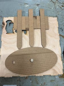
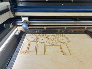
During our low-fidelity prototyping stage, we realized we would not be able to replicate the movement we wanted with cardboard. Our cardboard gear train would bind because of the exposed edges and it was difficult to visualize how the gears would interact with each other realistically. At this stage of prototyping, we decided to create a contingency in case the gears would not be able to produce the correct movement. Tiffany worked on creating a design and low-fidelity prototype of a cam/follower system that could push the stairs upward in a sequence rather instead of randomly. At the same time, Austin continued with the gear design and laser-cutted wood to verify if the train would function properly.
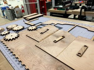
 Once our gears were printed and we were able to see them interacting with each other, we were optimistic that our design would work. We continued to work on other components of our model in Adobe Illustrator while finding times to laser cut our pieces. Occasionally we had to split up our prints because of the long queues at the laser cutter. For instance, Austin would come later in the night and Tiffany would come early in the morning to finish cuts. It wasn’t the most ideal situation, but we made it work.
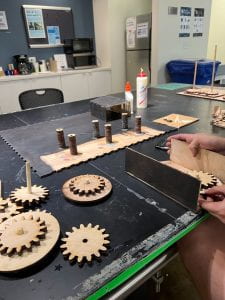
For our medium-fidelity prototype, we wanted to assemble the full gear train especially because it was going to be the main driver of our mechanism. We printed 2 layers of gears for better interactions, attached them together, used dowels provided by the OEDK, and printed the back board of our gear box in order to assemble this prototype. Although we had the other components printed, we assumed that the most challenging portion of our design was the gear train and so we focused our attention on that.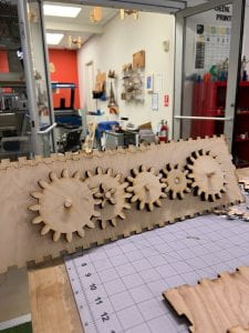
Once the medium-fidelity gear train was operational it was time to tackle the largest component of the project, which was the actual frame that housed our stairs and actuators. We used enmakercase.com to create our frame and gear box because we both liked the finger-locking system and decided that it would greatly help in the final assembly. Although we thought we planned for all possible scenarios, there were several times throughout the process where we would have to go back into Illustrator, revise our design, or laser-cut additional components (ex. spacers). It was definitely an iterative process as we were assembling our design and lots of hours were spent between the 2 of us.
As our deadline was approaching, we decided to divide the task that needed to be accomplished. Austin continued to work on the assembly (primarily interfacing the linear actuators to the gear train) and the water-jet cut while Tiffany worked on the post-processing and vinyl cut.
 After countless
 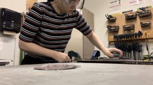 hours in the OEDK and a lot of blood, sweat, and tears… we were not successful in creating a functioning mechanical model. In the end, our linear actuators were the trickiest mechanism to achieve as they were unable to properly translate linear motion onto our stairs. Our gears, although functional, also had binding issues given the weight of the stairs and instability of the actuators. Needless to say, we were both really disappointed that our efforts weren’t met with a functional model but we both learned so much along the way.

Our presentation can be found here: Mechanical Valley Presentation
Video can be found here: Mechanical Valley Video
what we could improve on
There were a lot of areas that we could have improved on in this project. Scaling up and creating a large model, although intended for wiggle room, actually ended up creating more problems for us. We did not anticipate the weight of our stairs to be so heavy that our actuators would not be able to support the linear motion and cause binding in the gear train. If we were able to do this project over, we would most likely reassess the gear train and keep our model at a reasonable scale. This would have greatly helped us especially when it came to re-cutting pieces that were improperly assembled.
Another observation we had as a team was that we were too inflexible in our idea of accomplishing the randomized motion. Due to that, it caused us to go down a path that may not have been realistic given the project scope or our abilities… there were times where we discussed pivoting our approach but again, we were too invested in our progress that it seemed almost wrong to go backwards. Given another chance, we would heavily consider design changes and pivoting approaches.
cost analysis
Material
Wood: 3 sheets @$18.99 (1/4x24x48″) = $56.97
Wood Stain: 3 oz Dark Walnut wood stain @$9.99/8oz = $3.75
Wood Glue: 2 oz @$2.48/4 oz = $1.24
Dowels: 2 dowel sticks @$1.26 (3/8″ x 48″) = $2.52
Metal: ~$5.00
Vinyl: ~ $1.50
Labor
Labor: 35 hr@$7.25/hr = $326.25 @2 people = $652.50
Machine Use: 5 hr @$20/hr = $100
Total = $823.23
