For the first lab of ENGI 210, I deconstructed a IVAC IV Pump. This device is used by medical professionals to infuse fluids or medications into patients in ways that are impractical to do manually.
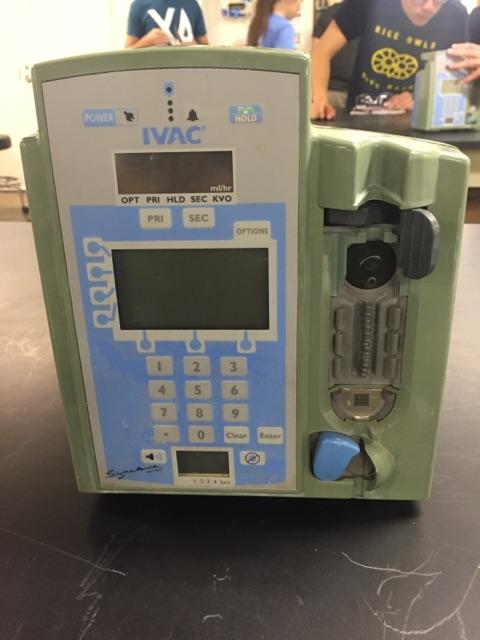
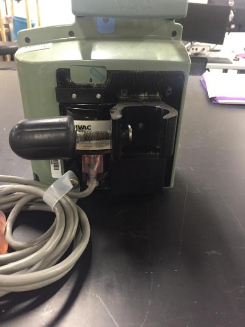
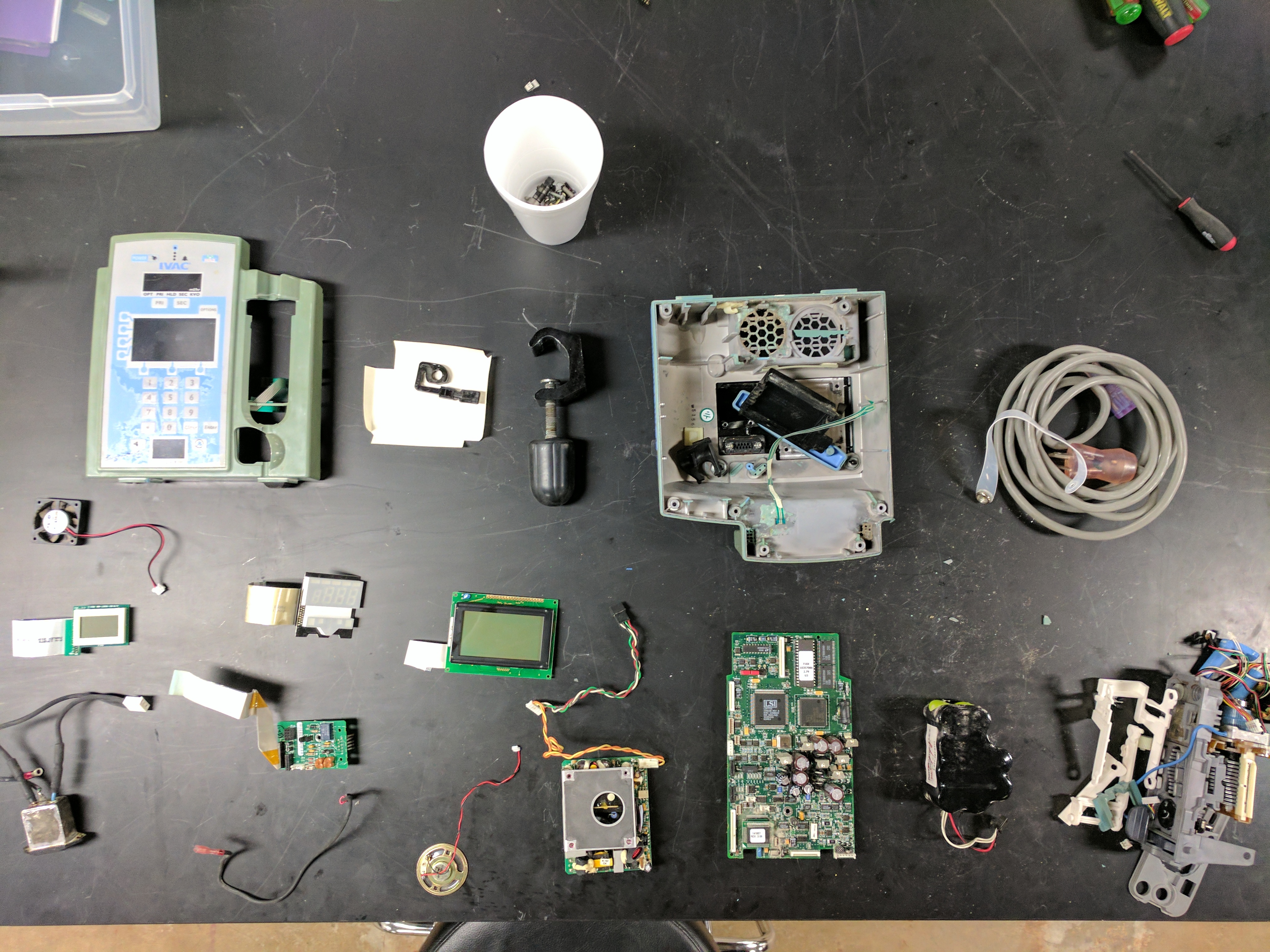
The IVAC Pump that I dissembled was enclosed in green plastic housing. 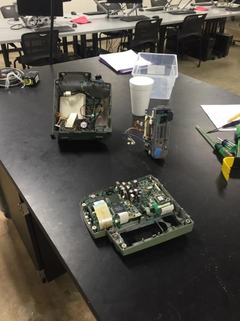 On the front of the device there were three different displays and a number pad. Then on the rear there was a large metal clamp, a power cord, and a large battery compartment. The plastic housing was held together by phillips head screws and a pair of snap joints on the top handle of the device. Once these screws were removed, my partner and I were able to pull the device apart into two parts. Inside, we discovered that both sides of the device housed large circuit boards. In addition, we also found the IV drip mechanism that consisted of a large motor and gear assembly.
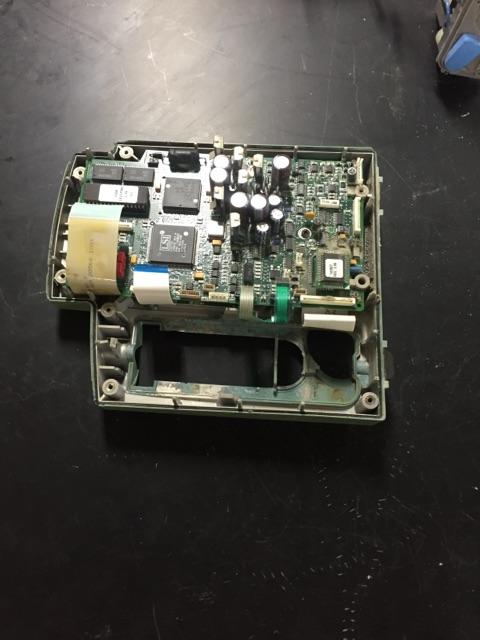 At this point, my partner and I decided to attack the front half of the device. We were able to remove the front circuit board by removing two phillips head screws and popping the board out of several snap clamps. Behind this circuit board, we discovered two LCD Screens and a VFD timer screen which were removed by disconnecting snap clamps. The large circuit board and different screens were the only components that my partner and I found removable from the front half of the device. We were unable to remove the number pad without physically breaking the front housing.
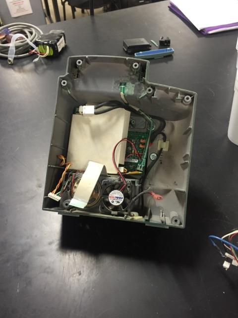 Moving onto the back portion of the device, my partner and I first removed the power cord and the battery pack from behind the rear of the green housing. We were easily able to remove these components by pulling the components out of their electrical plugs. Then inside the rear housing we turned our attention towards two smaller circuit boards. One circuit board was covered by a paper cover. These boards came out in a similar fashion to the front circuit boards. Each rear board was removed by removing one phillips head screw and popping several snap clamps. Behind these boards, we found a small fan, an alarm speaker, and the electrical plug for the power cord. These components were connected to the rear housing by snap clamps. At this point, my partner and I had removed all of the rear components and turned our attention to the actual pump/drip mechanism.
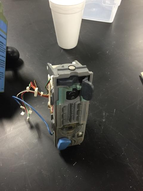 Sadly, we were unable to make much progress on the actual drip mechanism. Despite being a significant part of the device, this component was assembled very differently. The drip pump was primarily made of interconnecting plastic parts held together by snap clamps. This made the component very difficult to dissemble without breaking the interconnecting pieces.
All in all, my partner and I were able to learn a lot about this device by taking it apart. We believe that almost all the parts in the IV pump were custom made for the device. Most components held little or no resemblance to off-the-shelf consumer products. Despite this we found the device to be fairly simple to deconstruct due to its low number of parts and use of identical spec phillips screws. Through this observation my partner and I decided that the IV pump was designed to be taken apart and repaired. However, due to the complexity of certain components (mostly the IV drip mechanism and circuit boards), we believe that most repairs would be made by replacing entire components of the device. Once these faulty components were removed or the entire device itself was defunct, they were not made to be recycled. Again, because of the complexity of many components, my partner and I believe that recycling would be too difficult for practical application.
This lab was very enjoyable. I found that taking apart this unique piece of equipment to be very rewarding. In the process of disassembly, I was able to learn a lot about the way things are assembled and designed.