For our ENGI 210 midterm, we were tasked with creating a physical mechanical model of one of the 507 Mechanical Movements. For my 2D Drawing homework assignment, I drew Movement #96: the heart cam.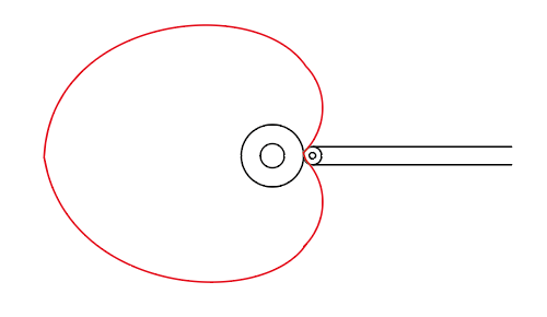
This movement incorporates both rotational and translational movement. The heart-shaped cam rotates around the center axis. Simultaneously, the peg and miniature wheel component move along the central horizontal plane away from and toward the center of the mechanism as the heart rotates.
I realized early on that further developing my 2D drawing was necessary in order to laser cut functional parts. However, further development of my design quickly became a creative, artistic brainstorming session, as well. I needed to incorporate some sort of aesthetic and visual appeal to this device. I also wanted the moving peg to be more than just a moving peg. The heart cam mechanism has a bit of a romantic connotation, so I thought it may be fitting to maintain this romantic aesthetic throughout my entire design. I then asked myself, “What is something romantic that has a peg/stick element to it?” Hmmm…….flowers!! I was immediately sold on the idea.
I initially made a few rough, preliminary sketches of what I envisioned for my project.

These sketches depict a vase-shaped structure supported on a base with the heart cam integrated into the lower half of the vase. My initial design had three flower stems joined together to form one peg that would roll over the heart cam causing all three flowers to move as one. The sketch on the right also depicts a piece that guides the stems movement and holds it in place vertically. A main design objective was to conceal the mechanism on one side of the vase, so that when operated, the flowers simply appear to be raising and lowering on their own if viewed from the other side.
After completely these preliminary sketches, I roughly sketched out the different components of the mechanism that I needed to draw digitally using Adobe Illustrator and ultimately laser cut. 
I first browsed the web for a vase shape appropriate for the various attachments and flower shapes that I felt also fit my envisioned aesthetic. After deciding on both a flower and vase, I simply downloaded the respective image files into Adobe Illustrator. I then used the image tracer tool to create the precise vector cuts I needed. Additionally, I was able to isolate the various paths within the flowers and assign a raster to these inner details rather than a cut. Moreover, I pulled my first cam drawing from my 2D Adobe Illustrator homework, making a few adjustments to the dimensions. The smaller various stem components are mostly rectangles created using the Rectangle Tool. I formed the main stem piece by culminating multiple arcs and lines into a symmetrical three-pronged stem. My initial plans are depicted below.
I ran my initial plans over cardboard for my first, low-fidelity prototype, assembling and adhering the pieces using hot glue. Overall, I was pleased with this initial iteration. The pieces all fit nicely and the cheerful aesthetic was already well-represented. However, I quickly realized that my current cam design was going to be difficult to successfully spin to create the translational movement. I experimented with a few different versions of various, wooden heart-shaped cams rather than cardboard for a more accurate representation. I also cut an additional stem and set of supports out of wood to form a more functional medium-fidelity prototype. However, I ultimately decided that a centered, oval-shaped cam would be a more effective, reliable mechanism over the heart-shaped cam. My medium fidelity prototype is shown below.

I presented this semi-functional, medium-fidelity prototype to Wettergreen at our prototyping checkpoint evaluation. He was rather content with my design and progress, but he did have a couple of suggestions. First, he suggested that I consider breaking the one stem with four flowers into multiple stems to create a more intricate, entertaining mechanism. Additionally, he suggested that I consider strengthening the base of my design.
I was appreciative of his suggestions and decided to implement both of them into my next prototype! I re-drew the stem components as well as the stem-support system, and I also added an second layer of material to the base. Within no time, I had a functioning three piece stem system and a sturdy multi-layered base.
 After finalizing and successfully integrating my enhanced stem design, it was time to plasma cut a component! I decided to plasma cut my oval-shaped cam because I wanted to minimize the amount of friction between the stems and the rotating cam in order to maximize my device’s ease of use. Wooden stems against a wooden cam creates much more friction than wooden stems against a smooth, metal cam.
I simply transferred the cam .ai file to a thumb drive and made my way to the machine shop! I snooped around the back of the shop for the thickest sheet of aluminum I could find. I then followed the proper protocol and steps necessary to successfully operate the plasma cutter. I then cut two identical cams out of this aluminum to allow for a margin of experimentation and error.
I took both cams out to the back of the OEDK and angle grinded the protruding dross off of the pieces and smoothed down the edges as much as I could. In order to create an even, homogenous surface on the cams, I decided to sand blast them, as well. Next, I drilled a 1/8 inch hole through one side of each cam that I would later insert a small dowel into as a handle to help spin the piece. With my metal pieces cut and semi post-processed and my mechanism design finalized, it was now time to decide on paint colors, methods of painting, and stylistic details!
First, I wanted the base of my mechanism to be more than just a rectangular plank of plywood. So, I decided to raster a checkered pattern across the entire piece to enhance its visual appeal. This pattern is meant to represent a section of a checkered table cloth on which the flower vase sits. I created this pattern in Adobe Illustrator by first using the rectangular grid tool. Next, I used the shape builder tool and switched the color setting to fill. I then selected every other box in alternating rows to create this desired pattern. I overlaid this pattern onto my base piece shown below.
I simply ran this file through the laser cutter, glued the piece to another plank of plywood, and coated it with polyurethane spray for a glossy, smooth finish!

Next, I decided that in addition to the rotational and translational movement created by the cam component of my project, I also wanted one of the flowers to spin independently, as well. Therefore, I re-cut one of my flowers with a 19 mm circular cut out in the center of it. This cut out accounts for the integration of a bearing that will allow the flower to spin.
I then dove into various stages of painting! I spray painted the upper halves of the flower stems green, the vase and stem support components a deep, calming blue, and the metal, sandblasted cam a nice teal shade. Next, I primed the flowers with acrylic primer. With a few shades of acrylic paint of my own collection, I created a subtle yellow shade that I used for the petals of the flowers. I filled the centers of three of the flowers with a deep brown and set them out to dry!
After all the paint had dried, it was time to assemble and adhere my various parts and components together. I began by press fitting bearings into both cams and the single flower with a cut out. I had a hard time press fitting a bearing to a even, level orientation into one of the cams, but the other cam accepted the bearing much easier and effectively. Thank god I cut two! I then used epoxy to fully adhere the bearings to these components.

I used wood glue to assemble the multiple stem and vase pieces as well as to adhere the flowers to the stems and the vase component to the base. The vase is press fit into cut outs in the base piece, but I used wood glue to further secure these components in place. Below are the left and right stem and flower components.

The center stem component has pieces of wood attached to the back and front to offset the center flowers from the ones on either side of them. Additionally, the front, spinning flower is attached to the center stem by a dowel component that is wood glued to the stem and epoxied to the 6 mm center hole of the flower’s bearing. This dowel piece is depicted below. 
I also wood-glued a 6 mm thick dowel into the hole in the center of the anterior vase piece for the cam to spin about.
Next, I measured and cut a crank handle from a 6 mm thick dowel to insert into the hole drilled through the cam. First, however, I sanded, stained, and applied a gloss finish to this wooden piece to enhance its appearance and feel. I then epoxied the handle into the hole in the cam.
My last step was to attach the finished cam component to the vase! I made sure the cam was level and slightly separated from the vase. Then, I simply epoxied the inner hole of the cam’s bearing to the 6mm thick dowel protruding from the anterior piece of the vase and let it dry.
I slipped the three flowers into their respective slots and spun the cam to observe my fantastic dancing flowers dance away! The three separate stems fluctuate heights in a wave-like pattern, and the center flower spins similarly to a fidget spinner which everyone knows is incredibly satisfying. These various translational and rotational movements culminate together to form a truly mesmerizing show!

From using Adobe Illustrator to various adhesives to the plasma cutter, this project was an intricate synthesis of all of the fabrication methods and tools I have learned throughout the semester. My mechanism represents much more than a functional representation of mechanical movement #96. After completing this project, I am even more confident in my prototyping skills as well as my navigation of the OEDK and its available resources. It was also loads of fun to assemble and creatively post-process!
If I were to sell this device, many factors would have to be considered and included in the price of my Fantastic Dancing Flower mechanism. As for materials, I ordered three bearings that cost about 10$ total, I used roughly 15$ worth of plywood, 10$ worth of aluminum for the cam, and 1$ worth of 6mm dowels. That comes out to a total of 36$ spent on materials.
As for a labor charge, I spent around 20-25 hours from start to finish over the course of a few weeks completing this project. Like I always say, because this is more of a hobby for me than an assignment or job, I only charge 5$ an hour. If rounded up, the cost of labor comes out to 125$.
I obviously used a number of complex machines and tools to complete this project, including the plasma cutter, angle grinder, sandblaster, and laser cutter. As for post-processing methods, I used acrylic paint, various sprays and finishes, as well as a number of adhesives to assemble the parts. I consider my machine and OEDK resource usage to be more of a rental relationship with the OEDK. These machines and most of the post-processing tools belong to the OEDK but are available for me to use. Therefore, in order to integrate these expenses into my final cost I have considered the fact that industry average for overhead, consisting of machine rentals, tools, adhesives, etc., is 15% of the finalized materials and labor pricing. This charge adds an additional $24.15 to the cost of the product.
In total, my Fantastic Dancing Flowers would sell for $185.15. However, it will more than likely be to gifted to someone special instead! 🙂
