The goal of this project was to create a mechanical device that would demonstrate one or more of the mechanical movements from . I chose the mechanical movement I chose for a previous project https://engi210.blogs.rice.edu/2019/01/27/movement-%F0%9F%92%AF/
My initial vision for this project was to use the quick return mechanism to modulate many tines to form sort of a wave front that a ball would be moved by. My intention was to use a reversing gear mechanism to reverse the direction once the ball reached one side of the device. Seeing the rapidly increasing complexity of this design, I scrapped the reversing idea pretty quickly and I was later convinced to remove the ball and to reduce the total number of tines from what I had at the time planned to be 20 to a much more reasonable 6. These reductions in complexity proved to be vital to the success of the project because even the reduced complexity version took a significant amount of time to finish.

The next step was to design the machine. I chose to use Autodesk Inventor as my cad program because it allows me to more easily choose dimension, layout the vector files than illustrator. More importantly however is it’s ability to do parametric modeling. This allowed me to keep several variables such as the laser kerf or actual wood thickness in an excel document, and then change them as needed. The model then automatically updates using the new values. This saved many hours when I did not have to manually adjust my designs for the correct laser kerf. I also made use of parametric to change overall machine characteristics such as the ratio between the fastest and slowest speed of the quick return or the vertical distance that the tines would move. This allowed me to see multiple options in CAD and then choose the one I liked the best.

Actually designing the parts was very simple compared to a typical part creation workflow because the parts only needed a single sketch and single extrusion. After the parts were made I assembled them with the appropriate constraints so that I could see a completed model.


After I assembled it and tested it with a couple of different model parameters I found a configuration I liked and the proceeded to move to laser cutting it. I started by cutting a few test parts to dial into the correct kerf. to do this I created a layout file with every part. This could be exported as a pdf and then imported into illustrator and then sent to the laser cutter to be cut. Because I defined these experimentally determined values parametrically, not only would the model automatically update, but so too would the layout file meaning the only work in trying many values for the kerf and other clearance values was to re-export them as pdf’s. It only took about an hour to try many different values to get the ones that worked the best.

The next step was to lay out all of the different parts I would need onto the same cut so that I could press go and have the laser cutter cut all of the parts at once. The first attempt did not go well because although a speed of 6 was working for individual parts when the machine was focused in the area of the part being cut, on a full sheet the focus changes too much to run at a speed much more than 3. the second pass didn’t line up with the first, so I decided to re-cut from a new sheet. This time I also decided to put masking tape over the wood so that it would burn the top and bottom surfaces.


The next step was to put it all together. I realized that I needed to cut dowels so I made a quick drawing of a bunch of lines with the correct spacing and then used these to cut the dowels in the laser cutter. after it was assembled it was evident that there were several design issues that would need to fixed in the next version.

the biggest issue was that the spiral cam that actuated the quick return mechanism was too flimsy. the deflections that resulted caused parts to bind, parts to run into each other, and parts to fall apart due to the stress they were put under. To fix this I made the circular piece that slides in the quick return mechanism much larger so that is could accommodate 3 connecting dowel pins instead of 2. the pins were also spaced farther apart and thicker wood around them so that the wood wouldn’t shear apart. This change also mandated larger plates to connect them. These changes resulted in a much stiffer spiral cam shaft for the second iteration. The next change I made was to decrease the ratio of maximum to minimum speed that the mechanism would move at. This had the effect the moving the slide piece farther from the fulcrum of the quick return which gave it more leverage to raise and lower the tines. another change was to use 3/4 in dowel for the gear axle and quick return fulcrum instead of two 1/4 in dowels and stacked wooden circles that went on the dowels. This made the machine significantly easier to assemble as well as being stronger. Another change I made was Increasing the wall and base thickness. I did this for a couple reasons, the biggest reason was to reduce the wobbling of the axles without reducing the clearance. Anther big reason was to combat the warping of the laser cutter wood. Although I tried to pick as flat of wood as possible, there was still significant warping. laminating multiple sheets together significantly reduces the warp. Lastly the increased thickness increases the stiffness of the frame which helps to keep all the parts exactly where they need to be. The last change was less to the design and more to how I post processed the pieces. In the second iteration I sanded down the tines as well as the quick return lever so that they had more clearance to prevent binding against the parts that retained them. I the set out to make these changes to the CAD model

With these changes having been made to the CAD model I proceed to fabricating the parts. Suspecting that this might be my final iteration I stained the wood before cutting so that it would have my desired finish straight off the laser cutter. I then taped up the pieces. A consequence of my design changes was that my machine now took 3 sheet of wood instead of just 1.
![]()
After I cut the first sheet I noticed that something about the parts seemed to be wrong. Upon closer inspection I noticed that there was a very noticeable slant along one axis. Fearing that an entire sheet of wood was wasted, I assembled two of the parts to see if anything was usable. Unfortunately, the slant caused the pieces to be about 6 degrees out of square. The entire sheet of parts I had just cut was unusable. When I told a lab tech about the issue they informed me that they were aware of the issue and suggested that I probably didn’t need to work to such tight tolerances and should just file everything down to fit. Furious that there was no indication anywhere that the laser cutter was having issues and that I would be set back a day because of a known issue, I cleaned up and left for the night to figure out what I was going to do to cut my parts. ultimately I decided to learn the glowforge laser cutter, and lay out the parts again for the much smaller bed size. Instead of 3 sheets on the epilogue cutter, the glow forge would take 11. (glow forge sheets are standard sized sheets cut into quarters). With this worked out I returned the next day to cut the parts on the glowforge. I actually found the glowforge slightly easier to use than the epilogue with it’s camera for cut alignment, auto-focus, and direct use of pdf.


Having cut the parts, I then moved onto staining and sanding them. I then glued together the walls and base. In order to line all the sheets up for the gluing I cut the dowels and used them to align the sheets. For the larger 3/4″ dowels I was using for axles, I had to just etch them and then cut them with a normal saw. The etch marks would be helpful for later assembly to maintain proper spacing. With the dowels in hand than the walls drying, I assembled the inner mechanism.


Even without the walls to stabilize everything, the spiral cam shaft could easily rotate and actuate the mechanism. I decided at this point to plasma cut the tines and replace the wooden ones. I exported the tine into illustrator and then used the illustrator file to prepare the cut. after I plasma cut the part, I processed off the dross and sandblasted it for the final finish.

After finishing the tines, I disassembled the tines block and reassembled it with the new metal tines. Because the new metal tines were much thinner than the wood ones, I quickly cut acrylic spacers. the spacer thickness and metal thickness added up to the thickness of the wood tines maintaining the clearance I had designed for.

With all the parts ready, I loosely assembled everything for a final fit test. I found that without any lubrication, the machine wasn’t too difficult to actuate.
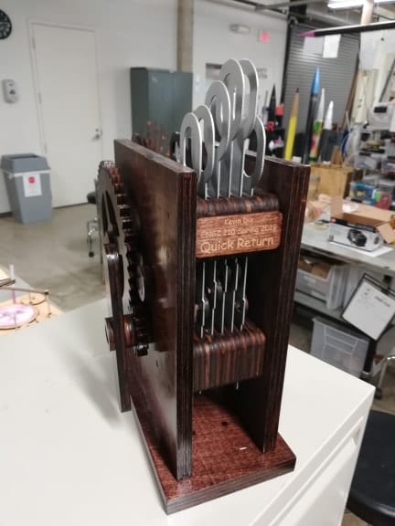
Satisfied with the fit, I took off the gears and knob on the outside of the machine and put several coats of polyurethane one them and the outer surfaces of the frame. Once the polyurethane was done drying, I put the gears and knob back on with the proper spacers. I then applied glue to all of the parts that were meant to be permanently fixed. This included the entire spiral cam shaft and the gears. I then applied Vaseline to the bearing surfaces which significantly improved the smoothness of operation. Overall the machine came out looking great. My intended aesthetic was clean and simple, such as to not distract the eye from the main focus which is the mechanism itself. The final product certainly embodies my desired aesthetic.
With the amount of time I spent on this machine, I will combine the cost of machines and small consumable items such as glue and finishes into a cumulative cost of 10$ because they were found to be very cheap in other cost analyses. The exception for this is the plasma cutter and laser cutter because their cost is much larger to use. The time I spent on the project has varied from day to day, increasing as the final deadline approached and on the weekends. A conservative estimate therefore of the average time spent each day is about 3 hours. The project was assigned on February 7th and I finished it on March 4th. That totals to 25 days or 75 hours. At a rate of $20/hr the labor for this project is $1500. An hour on the plasma cutter is 75$. The cost of laser cutting is difficult to estimate because it ‘s based on the line distance cut. I will therefore give a very rough estimate of 500 inches cut during the duration of the project. At about 15¢/in that brings the price of laser cutting to about 75$. I used 7 sheets of wood, 4 1/4″ dowels and 1 3/4″ dowel for this project which brings the wood cost to about 42$. Altogether the total cost to produce this mechanical model was about $1702.
If you would like to make this yourself, the plans for an all wood version are below:
full BOM v2 glowforge v2 long panel 1-1jf93r5 – 12×20 1/4″
full BOM v2 glowforge v2 long panel 2-1247hjl– 12×20 1/4″
full BOM v2 glowforge v2 panel 1-1ouk003 – 12×16 1/4″
full BOM v2 glowforge v2 panel 2-15llhp0 – 12×16 1/4″
full BOM v2 glowforge v2 panel 3-qsgaas – 12×16 1/4″
full BOM v2 glowforge v2 panel 4-247pagk – 12×16 1/4″
full BOM v2 glowforge v2 panel 5-1sbfhl1 – 12×16 1/4″
full BOM v2 glowforge v2 panel 6-2aiyhhx – 12×16 1/4″
full BOM v2 glowforge v2 panel 7-2kose3p – 12×16 1/4″
full BOM v2 glowforge v2 panel 8-1ltb4mv – 12×16 1/4″
full BOM v2 glowforge v2 panel 9-1bihf47– 12×16 1/4″
dowl cut v2-1n9pztx-1/4″ dowel
shaft etch-1lstvtg-3/4″ dowel
https://www.homedepot.com/p/1-4-in-x-48-in-Wood-Round-Dowel-HDDH1448/204354367
https://www.homedepot.com/p/3-4-in-x-48-in-Wood-Round-Dowel-HDDH3448/204354370
