The moment had arrived, after weeks of learning to use and practicing how to use equipment around the OEDK and Illustrator, we finally had the skills and experience to be ready for the midterm project: selecting a mechanical movement and building it using high quality materials, making use of our new knowledge and skills. The challenge was there, but I was prepared to face it, the homework had prepared me… Or at least that’s what I would say if I had done the all the homework by then. Instead I was faced with a lot of work and need of practice. Regardless, we all took on the challenge, here is how it went for me.
Part I: Selecting and Modeling mechanical movement
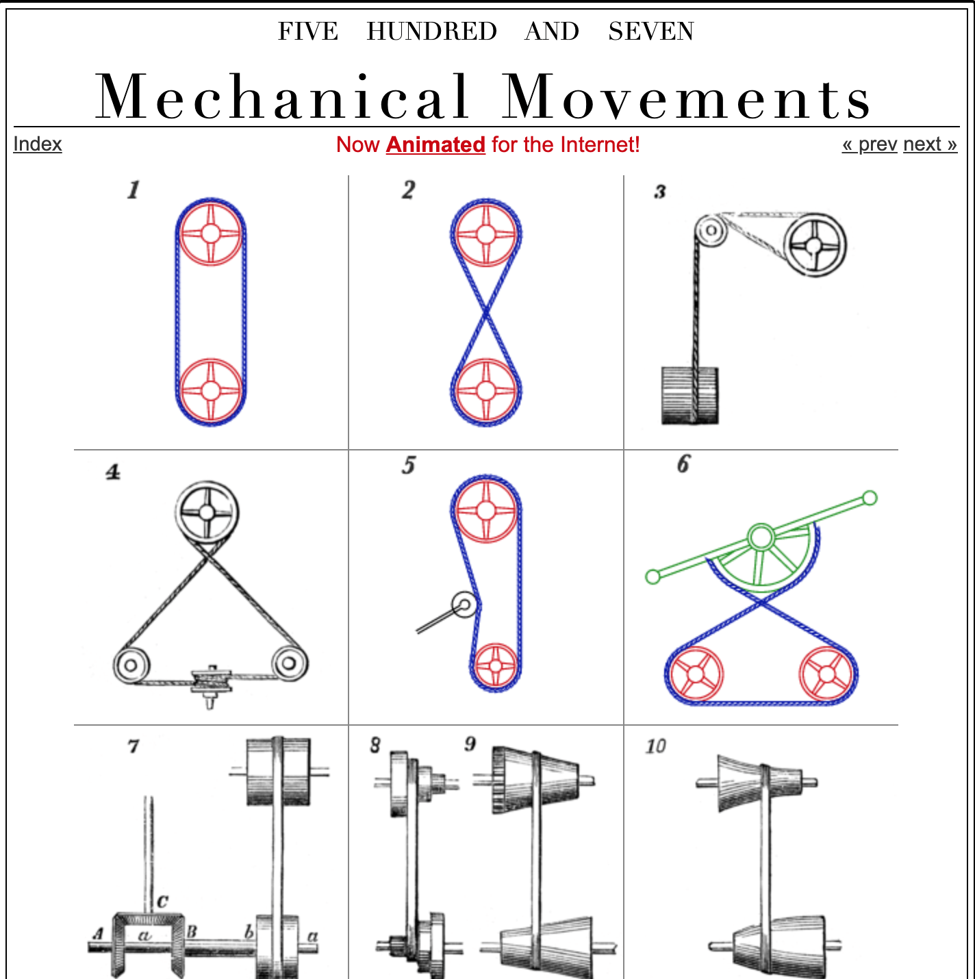
I began by going through the website 507 mechanical movements and choosing which movement would be best for me. While browsing through the movements, I heard Dr. Wettergreen mention that gears were not advisable, and so I narrowed my options to those without gears.
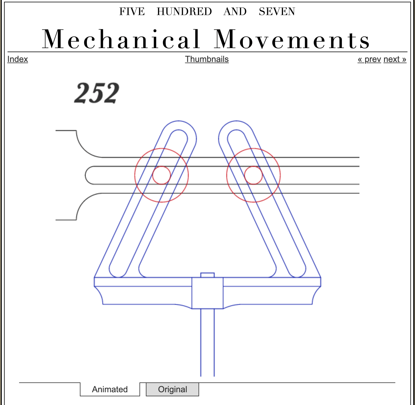
I ended up landing on movements 138 and 252, neither of them had gears and I believed that I could combine them to make a more complex mechanism without too much added effort. The idea being that 138 would move 252 up and down, connected by a shared rod.
Next we had to actually model these movements in Illustrator to flesh them out in to all their parts and be able to cut them out (machines like the water jet, laser cutter, and plasma cutter use vector files). Both my movements use some curvy and irregular shapes, for which I used the pen tool. It took me VERY long to get used to how to make curves in Illustrator, but I finally mastered it and now feel quite comfortable using the curvature/pen tool.

At this point I showed Dr. Wettergreen my models and he suggested I only do movement 252 instead of combining them since I would most likely find it challenging to make that one work smoothly. I agreed and proceed using only movement 252.
Now that I knew exactly what movement I was doing, I began to design the rest of the project, adding things like a support, a base, making it more aesthetically pleasing; and started considering potential issues such as weight of materials, their size, limitations of the motion, etc. All of this I tried to add and account for in my final model.

Part 2: Low Fidelity Prototyping
It was time to move from 2D models to actually physically building the midterm, or more like a proof of concept, a low fidelity prototype using low quality materials.
The first step was to cut out all the pieces out of cardboard using the laser cutter, I made a file and organized all the parts to reduce waste of material. I was wondering how I would make the bottom base, and was lucky enough to find a long box in the basement from which I cut off a piece to use.

I then gathered some superglue and some hot glue, and got to work assembling the prototype. All the time I spent planning my design ahead of time paid off as I was able to easily and efficiently build my low fidelity prototype almost exactly as I had planned it out. I had not used any exact measurements for my design, only eyeballed it so all the pieces seemed about the right size for each other (which makes me feel like I got lucky and should really consider measurements for my next project), then I scaled all of them to what I considered a reasonable real-life size.
Only three small things had to be modified to improve the design. The first, was that the foam (blue thing in 2D model picture) was now wrapped around the dowel and there was no spike, friction would prevent the mechanism from sliding too much. The second was that the rod now had a pointed edge at the bottom in order to make it easier for it to slide in to the hole on the box on which it stood. And the third, the biggest, was that I had to reinforce the horizontal piece because the cardboard was too weak to hold the triangle piece. These three changes improved how smoothly the mechanism operated, and I was quite happy with how it turned out.
Part 3: Now make it for real
As I mentioned before, I used no exact measurements and had only a rough idea of what they may be (14″ in height for the support, about 5″ in base for the triangle-looking piece, and 3″ height for the base box). But given how well everything fit in my low fidelity prototype, I used the same files to cut out all my high quality pieces.
Once again, the first step in the process was to laser cut all the wooden parts of my design, the support, rings, horizontal reinforcement pieces, and base box (I did not cut out the lid as I still wasn’t certain where everything would go or how big things like the support would be). Added to this were 10 rings with an inner diameter that fit the dowel exactly (I used the same ring size as for my low-fidelity prototype). These rings would be glued in a stack and guide the dowel in to the hole in the box to prevent it from getting stuck on its way down and from coming loose on its way up. To make the wood more appealing, I chose to use mahogany stain on the support material and the rings. I also cut out two acrylic pieces to create a sort of window within the support, these are held in place by pressure and a bit of super glue.
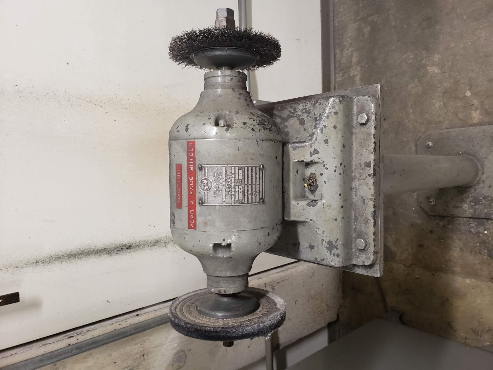
Then I moved to the wet-lab to cut out the triangle-looking part from a metal piece, this is the most complicated part of the mechanism, so I needed the precision of the water-jet. I made a mistake and typed in that my piece was .9″ thick, so the waterjet was going to take 70 min and use 18 lbs of abrasive to cut the piece. Luckily, I noticed my mistake before wasting all that material and corrected it. I had planned on angle grinding the pice, since I like that finish. I tested a piece of the same material to see how it would look, and to my surprise, this metal was very soft and quickly got chipped away by the angle grinder. Therefore I use a wire brush angle grinder to give the actual piece a grainy look.

The horizontal metal piece was cut using the plasma cutter and again I used the wire brush angle grinder to remove the dross and give it a nicer, smoother, look.
I finally had all the pieces I needed and was time to start putting things together. I used wood glue to make the stack of rings and build the support of the mechanism. I used Epoxy (smells horrible) to glue the metal horizontal part and its wooden reinforcement (more as an aesthetic piece now) together. Then use epoxy again to attach the compounded horizontal piece to the vertical support.

Afterwards I got a wooden dowel of about 9″(again, I guesstimated all measurements), made a smooth ballpoint on one end, and sawed down the middle of the other end (vertically) so I could slide the triangular piece down and glue it to the metal using epoxy. The saw did not make a gap big enough, so I had to sand dow the gap for the metal piece to fit, then I glued it with epoxy and a bit of superglue afterwards.

The next step was to make the “wheels” and use them to attach the triangular piece to the horizontal one. This is where the issues began to occur, as my first wheels had too much space between the front and back, making them slide very wobbly and get stuck when they would tilt too much. So I made them shorter, but this time they were too short and this resulted in too much friction between the horizontal piece and the sliding wheels. I found a medium length and fully expected it to work, but now only one wheel was getting stuck over an over again.

I thought it could be that the metal was cutting in to the wooden rod part of the wheels. But as it turns out, the issue was that my triangular piece was lightly warped on one side due to the angle grinding. This was causing excess friction so I used pliers to straighten it out and voila! the wheels slid effortlessly through the horizontal piece.

All that was left to do was to cut out the lid for the base box, I made a rectangle by using the files I had fro the support piece and cut it out from the lid file of when I originally made the base box. I also used the same diameter for the rings, and cut out a hole that big in the center of the box. Last step was to raster my name in to the corner of the base box.

One more issue occurred, and it was that my box turned out to be too tall, so my support was too low, when slid in to the box. To fix this I cut out 4 rectangles that I scaled to be slightly smaller that the rectangular cut in the base box, and glued them to the bottom of the support, giving git an extra inch in height. These rectangles remain hidden inside the base box. I put glue on the bottom rectangle, slid this compound support piece in to the base box, glued the ring stack to perfectly align with the center hole, and slid the vertical rod in to the stack. My midterm project was completed.

Cost Breakdown
Materials:
- Plywood: $10 (two pieces of 28″ x 32″ x1/4″ plywood)
- Aluminum sheet: $18 (online metals.come)
- Wooden Dowel: $1 (Woodpeckers C.)
- Acrylic: $3 (Hobby Lobby)
- Stain: $7 (Minwax, Walmart)
- Wood glue: $4 (Gorillaz 8oz, Home Depot)
- Super glue: $1 (Zoro)
- Epoxy: $5 (Amazon)
Machine usage:
- Laser cutter: $40 (at $60 per hour, engineerable.com)
- Plasma Cutter: $22.5 (at 135 per hour, HercRentals)
- Waterjet: $20 (at $40 per hour plus abrasive cost)
- Angle Grinder: $20 (Wal Mart)
Designing:
- Adobe Illustrator: $20 (monthly rate)
- Making 2D model: $15 (at $10 per hour)
Labor:
- Me: $120 (at $10 per hour)
- Someone who knows what they’re doing: $60 ($10 per hour)
Total cost: $286.5
