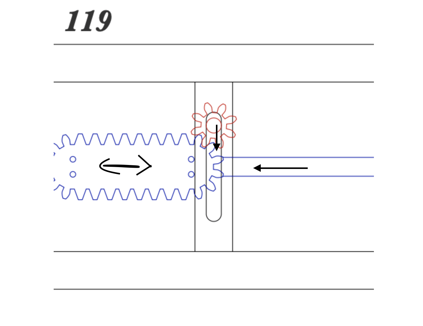
The midterm for ENGI 210 is meant to be the culmination of all the skills we have learned up until the midway point in the year. We were tasked with creating a working mechanical model of our choosing. I decided on using mechanical movement 119. This movement includes a smaller gear, or pinion, that moves along the endless rack in the middle. The small gear is held in place by a vertical track and when the gear it at the top or bottom, it moves the rack left or right. Once the rack is at the furthest extent of its motion, the pinion moves up or dow, then begins moving the middle rack horizontally again.
The Design:
Once I had my heart set on a movement to pursue, I brainstormed what kind of designs I could do to make the project have a theme or purpose. I knew I wanted the design to incorporate something from the mountains or the ocean since those are two of my biggest interests back home. When I thought about how the small gear would always be rotating at the top, I had the inspiration to make spokes with Dolphins on the end so it would appear that they were jumping out of the water while the waves were moving back. This would give the impression that the dolphins were moving forward in the water given that pinion could not move horizontally. While working on the design for the low fidelity, I finally realized that the long blue rectangle that was inline with the rack was actually an open slot in a board and not a long bar attached to the rack.
Low Fidelity:

Cardboard cuts
I was not expecting to learn much from the low fidelity prototype given that the cardboard was too weak and had too much friction for my gears to even come close to working. However, It did reveal some useful insights about the sizing or my parts. Luckily the pieces like the rack, pinion, and waves were already about the size I wanted them to be. Once I assembled the model I figured out how I would attach the dolphins to the gear.

Cardboard Assembled
I learned that I would have to attacked the dolphins on top of the small gear so they wouldn’t interfere with the rack. This showed me that the vertical track would have to offset from the rest of the system and that I would have to lengthen the bottom of the vertical track to accommodate for the added length of the dolphins on sticks. Another change I made after making this model was to create a single wheel that had all the dolphins on it, rather than gluing them all on individually.
Mid-Fidelity:

Mid fidelity Components
The main goal of the mid fidelity prototype was to make sure the device could function. Since I had heard that many people in the pst have had issues with their gears not meshing correctly, I was very worried about how my gear and rack would turn out given the added complexity of horizontal and vertical movement.

Mid-Fi Back

Rack Slider
In order to ensure that the middle rack was restricted to only moving horizontally, this slider was added. I Performed some tests and my worst fears were confirmed when the gears did not work with each other. There were a couple of issues I had to tackle before the prototype would be close to working. These issues included:
1. Length of slot in vertical tack
2. With of slot in horizontal track
3. Friction preventing motion
4. When rack was at end of horizontal track, gear could not re-engage and bring it back
I began eliminating these problems one by one by making adjustments in the illustrator files. After 4 Iterations of the vertical rack I finally had it lined up perfectly so when the pinion was at the bottom or top, it would fully engage with the rack. I then measured the max distance the middle track would have to be by lining up the rack and the pinion parallel to each other in the middle, then finding the distance from the acrylic slider to the end of the current track. The issue of friction was pretty easy to solve with some Vaseline added to the horizontal track.
After addressing the first 3 set backs, the middle rack move relatively smoothly along the horizontal rack while the pinion was being spun; however, once the gear had been pushed fully to one side, it would remain there and the pinion had no means of re-engaging. This issue can been viewed in this video:
I was starting to question my rack and pinion parts and made another design with new gears with different angles. But when I tested the new rack and pinion, the didn’t work either! I looked at the metal racks and pinions that were in the parts drawers but I knew trying too weld this rack together with 2 gears would have been another nightmare so I abandoned that idea. At this point, I was extremely worried that I had chosen my mechanical movement incorrectly and that I should have settled for something that could have been made entirely by gear generator.
I figured it was time to try test the prototype while it was standing to have a better idea of how to solve the issue of the rack being too far away. Once the design was propped upright, additional pieces of wood were attached to this slider on the other side of the horizontal track to keep the rack from falling out.

Stabilizers glued to slider
I placed pieces of cloth in between the track and stacked stabilizers so they would not glue to each other.
The Breakthrough
I showed my progress to our TA Adulfo, a living legend. (Thank you for all your help during the semester and this project) He suggested that I could try attaching a spring to the front pieces of wood that I just glued on as to not interfere with the gears and rotating dolphins in the back. After some more planning, this idea was changed to having a spring at each end of the horizontal rack and having the front stabilizers compress them for a few seconds, then return the rack to a portion far enough into the middle for the pinion to engage with the rack and move it horizontally again. Once this idea was solidified, I finally felt like there was some hope in getting the project to work.
The Springs
Even though I had confidence the springs would work, implementing them properly would be more of an issue than I had anticipated

First Springs
I put this first round of springs/bumpers on and they compressed fully with the stack of wood attached to the middle slider, but the springs were not long enough to push the rack into a suitable position. Before admitting to myself I needed to find and glue a new set of springs, I tried to attached another small spring the one that had already been glued in. After a few minutes I got a spring to stay stacked to the first but it immediately popped out when met with any pressure. I soon found a new spring that was the length I needed but it was a little too strong for the crank motion to be smooth. This was a tough point for me in the in the project because I knew I would have to sacrifice ease of operation for functionality.
I tested with the longer springs and it finally worked! Yes it required more effort while the spring was being compressed, but I was so happy that I had made it to a point where the the project was capable of working.

Long Springs on the Board
But the more I kept testing, the more one spring would bend and pop out the side when it was compressed by the stack of wood. Upon inspection It appears that the epoxied spring was set at a slight angle and that angle would case it to pop out to the side once it was almost fully compressed. For a while I tried to put it off since I didn’t want to confront the idea that the solution I was so proud of having was flawed. But I knew pretending like it wasn’t there would not help me when the project was being graded so I made 2 more spring blocks that could maybe do the job better. Once they were dry, I tested them and they were both so straight that they would never bend out no matter what kind of irregular compression pattern I threw at them. I had to pry off the previous spring block which unfortunately damaged the wood, but all the components were already attached and etched to this board so I accepted it. I then attached the next spring block and waited optimistically.
Once I thought I had the main functionality squared away, I moved onto cutting out my metal Components.
Plasma Cutting
I had decided that the plasma cut section of my project would be aesthetic and more specifically the waves. I plasma cut out the waves without much trouble and based on my experience from the plasma cutting homework, I made sure to pick a magnetic metal so I could angle grind it outside. I Angle ground both sides and gave it a semi wavy patter on the metal. However this was mostly covered up by the coats of blue spray paint I put on.

Plasma Cut waves before spray painting
Water-jet Cutting

WaterJet
For my functional Water-Jet part, I made two of the vertical tracks that would guide the handle connected to the pinion. Cutting out these pieces were a little tricky because the was not a lot of room to fit the 2 tracks and the splash guard would run into the clamps during the dry runs since the pieces ran almost the full length of the metal. Luckily I was able to find another piece of aluminum with equal thickness but was 50% longer. After listening to the water jet cut for nearly half an hour, the pieces were ready and I put them into my base where they fit well.

Vertical Tracks in base
Once the tracks were in the base, I stuck 4 dowels through some washers to keep the vertical tracks from leaning in or out.
Adding the Handle
For the entire project I had been using the same dowel for all testing, but once I had set in my 2 vertical tracks I knew I would be time to finally make the handle and crank officially glued in. Since I was getting anxious and wanted to do some final testing with the crank, I pushed through this step faster than I should have. I was running under the assumption that the glue I was using to hold my crank components together would take an hour to dry before I could put it under the kind of stress needed to complete there movement. So once I started the glueing process for attaching the Dolphins Ott the back of my pinion, I tried to cut out, attach and glue as much of the handle as I could do during the time so I wouldn’t have to wait even longer before testing. Here is where I made a critical error. While I was focusing on how to keep the handle supported well during the drying process, I forgot to put the 4 washers along the handle so it would remain perpendicular with the vertical track. Once the components had dried I realized my mistake but all the components had been set in place. I attempted to make a couple half washers that I could add to the handle next to the track, but the glue was not working well and the pieces kept splitting or sliding away from where they should have been. because of this, the user has to make sure they are keeping the handle perpendicular to the vertical track.

Handle missing Washers
Finishing touches
Once the handle was set in, I stained and wood glued the base together. Then I epoxied in the other tracks that inserted into the base. Once everything was dry I got these videos of the model working.
While my replacement spring block did not work perfectly, it still managed to push the rack far enough into the middle for the pinion to easily engage and keep the movement rolling. The main issues while operating this device is that the user has to be attentive as to when they need to move the pinion up or down and to keep the handle straight. Other than that, I am still proud of what I made. I’m glad that I challenged myself and went for a movement that I had the most creative inspiration for, even if it added a lot more work.

Cost Analysis
Labor: 32 hours x $15/hour = $480
Materials:
1/8″ plywood, 24″ x 32″ (OEDK) $5.00 x 5 = $25
6″x24″ 1/4″ thick Aluminum = $16.98
3x epoxy adhesive = $9.45
Machine Time:
Total for Plasma, water jet, and laser cutter: $23
Total: $554.43
= way too much money for something that is not super polished
https://www.lowes.com/pd/Hillman-6-in-x-24-in-Aluminum-Solid/3050449
https://www.zoro.com/super-glue-epoxy-2-part-instant-ylw-1-oz-syringe-sy-in48/i/G1266483/feature-product?gclid=EAIaIQobChMIhcKpjrOv5QIVz4CfCh0vPwAgEAQYFCABEgIS2fD_BwE
