“I want to make something with gears. I don’t know what yet, but something that looks nice.” — me on day 1 of this semester…
“Why do you build me up, buttercup, baby…” — The Foundatons “Build Me Up Buttercup”
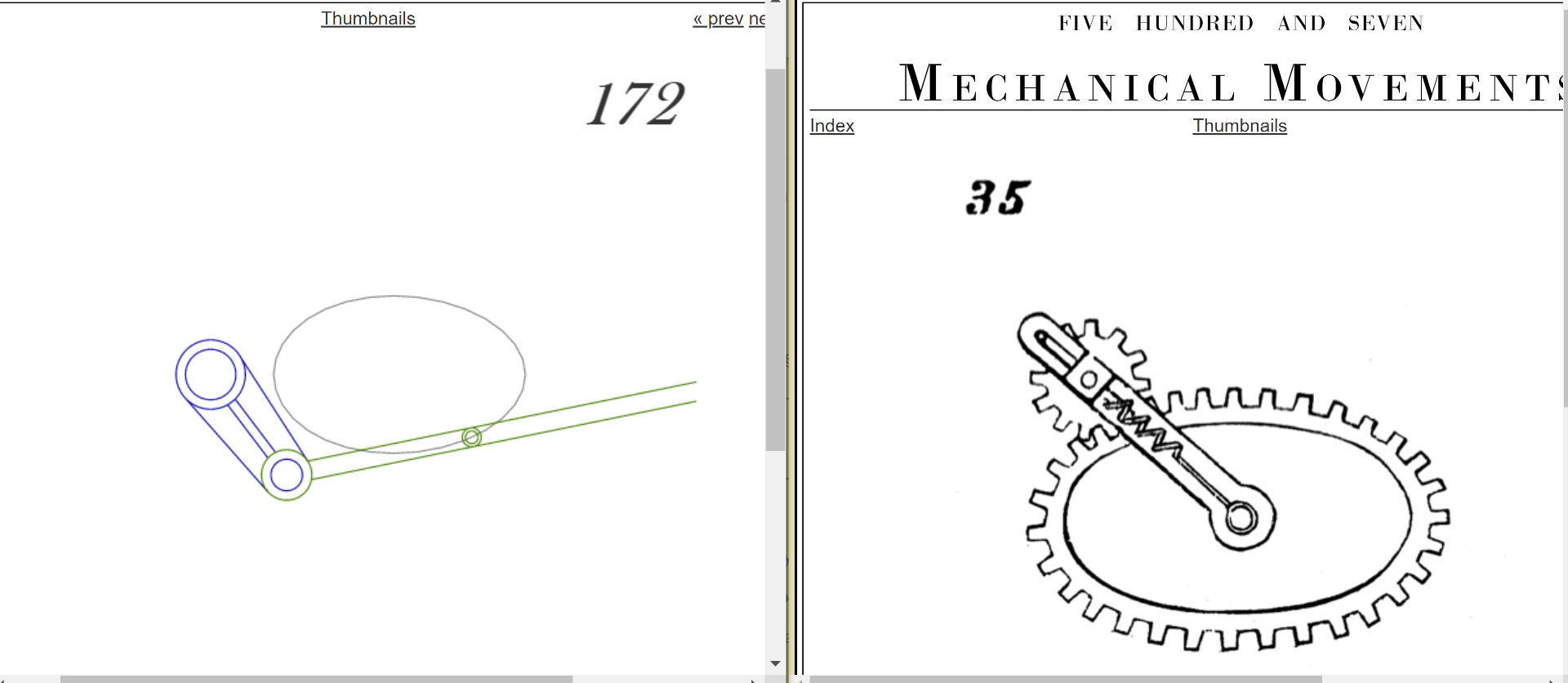
The gear mechanism I initially chose was #35 from 507 Mechanical Movements, and my plan was to drive the system using mechanism #172. Inspired by an early morning bean bag chat with my suitemate Rachel, I wanted to have a ballerina stand on top of the circular gear.
“…just to let me down…”– The Foundatons “Build Me Up Buttercup”
The problem, however, is that the shape of the path in 172 is not a regular oval, so it will not line up with the motion of the circular gear in #35
This was discovered after the failure of the first low fidelity prototype in which the circular gear consistenly got stuck at the same point.
“…and mess me around…”– The Foundatons “Build Me Up Buttercup”
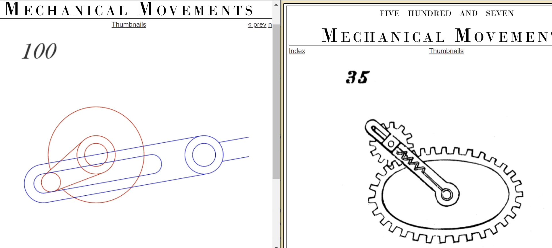 While talking about this concern with Adulfo, both of us thought of attaching the driving mechanism to the tip of the arm in #35 instead of to the center of the circular gear. This way we also have a fixed radius, and will switch from #172 to #100.
Unfortunately, the blue arm in mechanism #100 will have to pass through the center of the path, where the ballerina would be… We also considered having #100 beneath #35, but that wouldn’t work either because of the lack of necessary support at the bottom of the system.
“I need you, more than anyone, darlin. You know that I have from the start…”– The Foundatons “Build Me Up Buttercup”
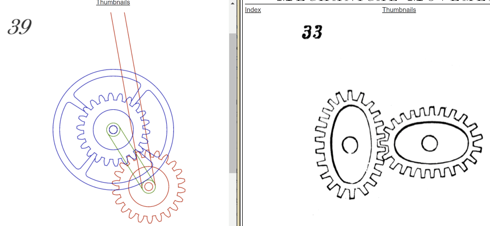
After many hours of researching, playing with gear generating sources, and staring at the wall, I decided to combine #39 and #33 to form an elliptical planetary gear mechanism.
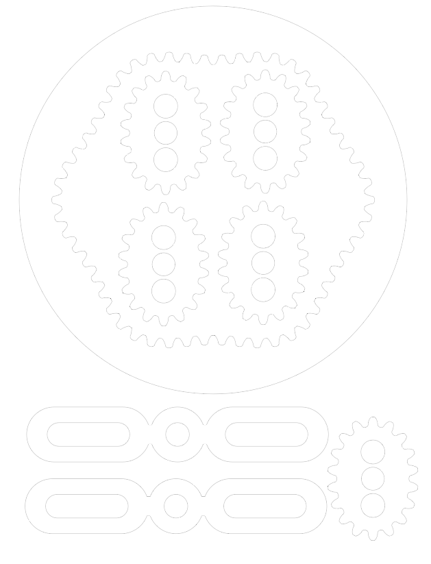
I created the dimensions for the CAD file and 2D drawings with the help of grabCAD. Everything is looking good in 2D, now onto cutting and actually fitting the pieces together.
“So build me up, buttercup, don’t break my heart…”– The Foundatons “Build Me Up Buttercup”
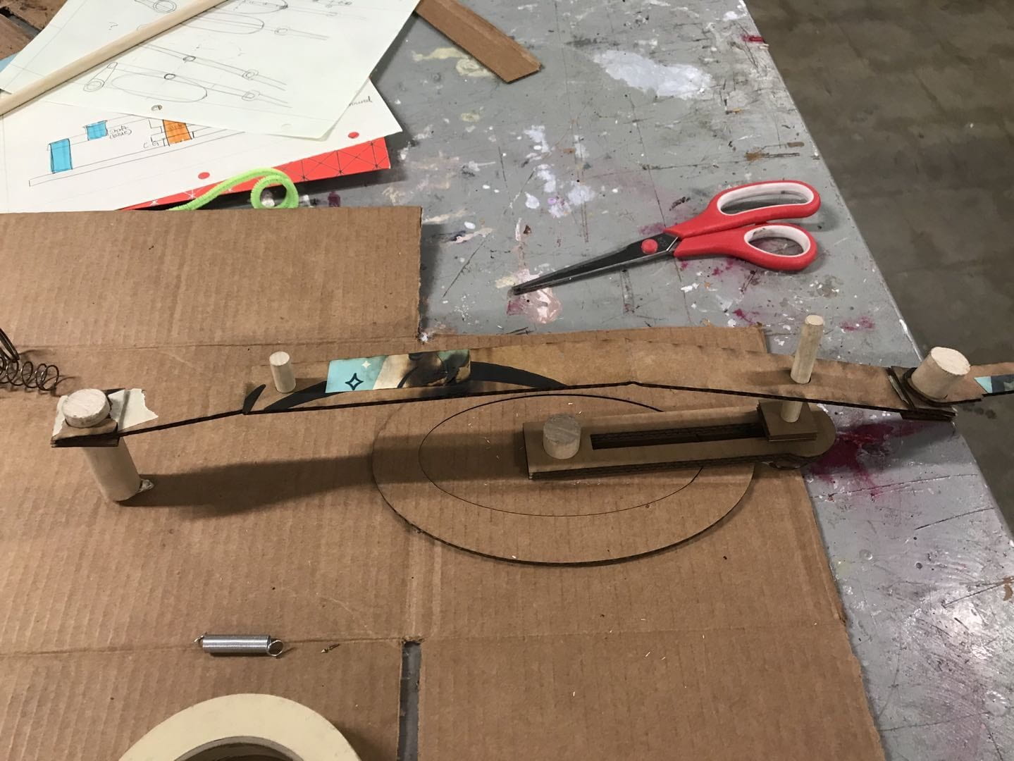
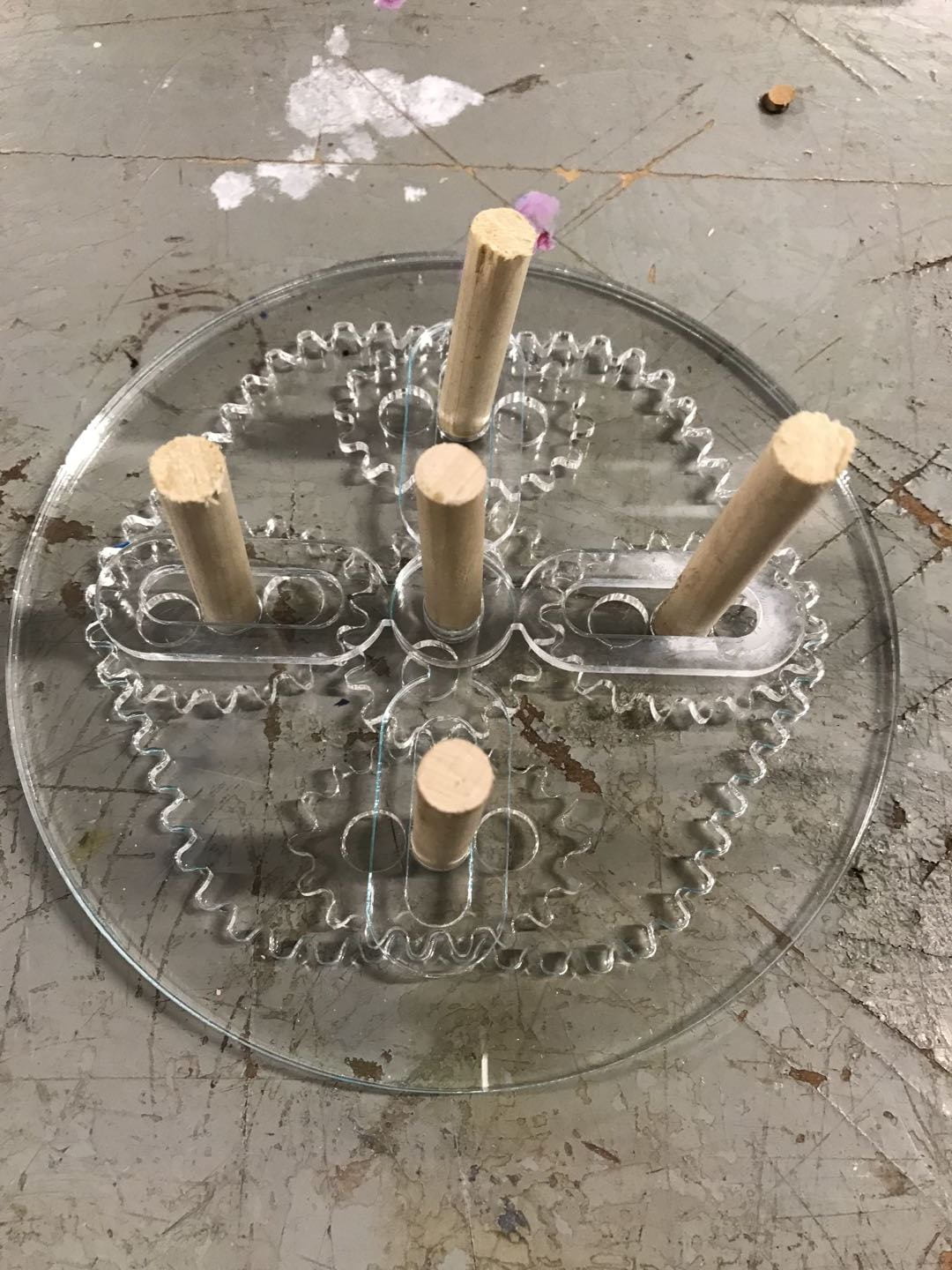
The first iteration was made with wood, and as expected, it did not turn very well because of (1) the friction between wood surfaces and (2) the unwanted upward motion of the central gear. The first issue was addressed in version 2 by changing the material to 1/8″ acrylic and the second issue was resolved by fixing the central dowel onto the bottom plate as well as thickening the gears for a larger area of contact.

What makes Doris smile like a fool for the entire day? Her gears finally turned:
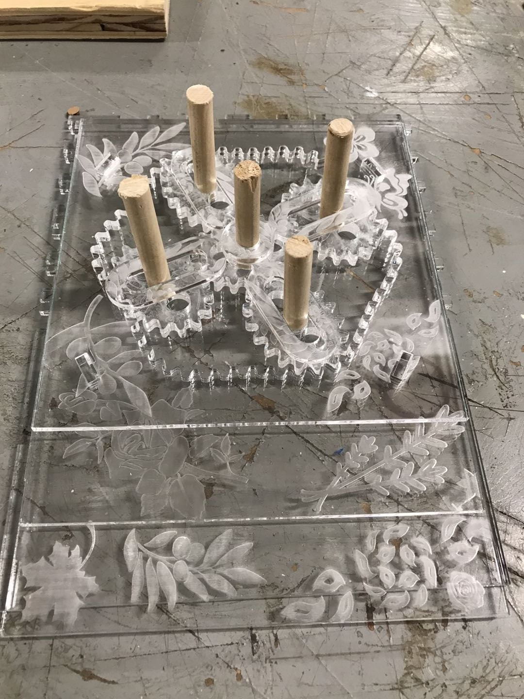
While showing this prototype, my audiences and I both noticed that a couple of gears could pop up easily and then lose the specific alignment needed for turning :/ I took Dr. Wettergreen’s suggestion and modified the arms so now they are wider to cover the gears up and keep them down.

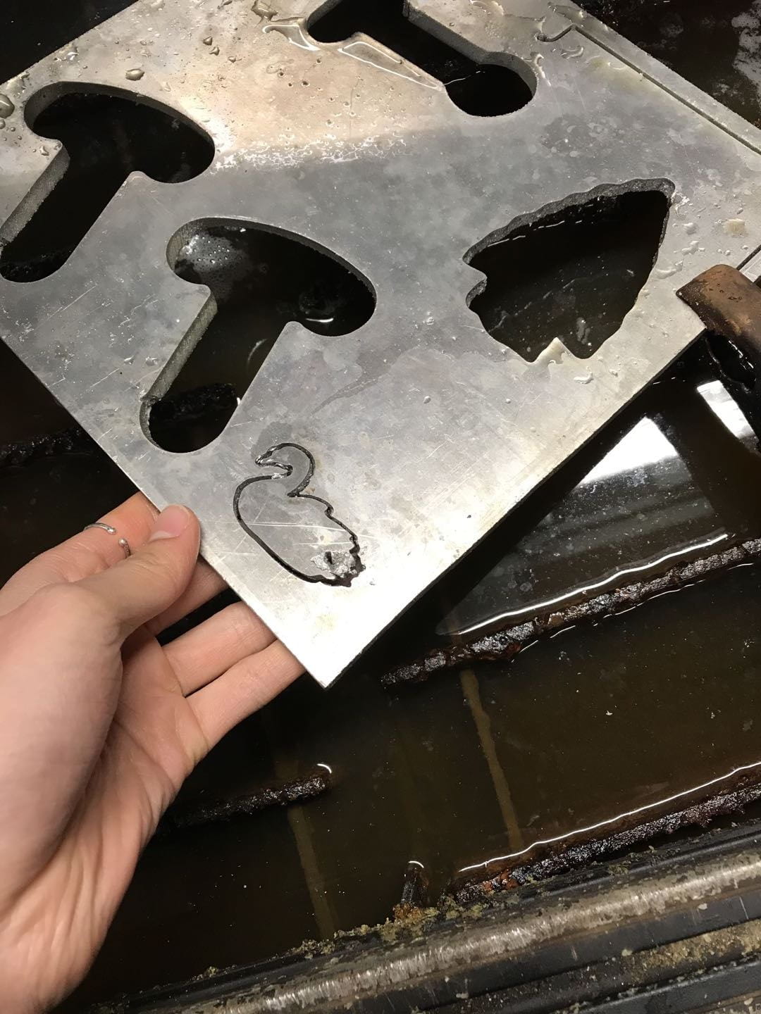
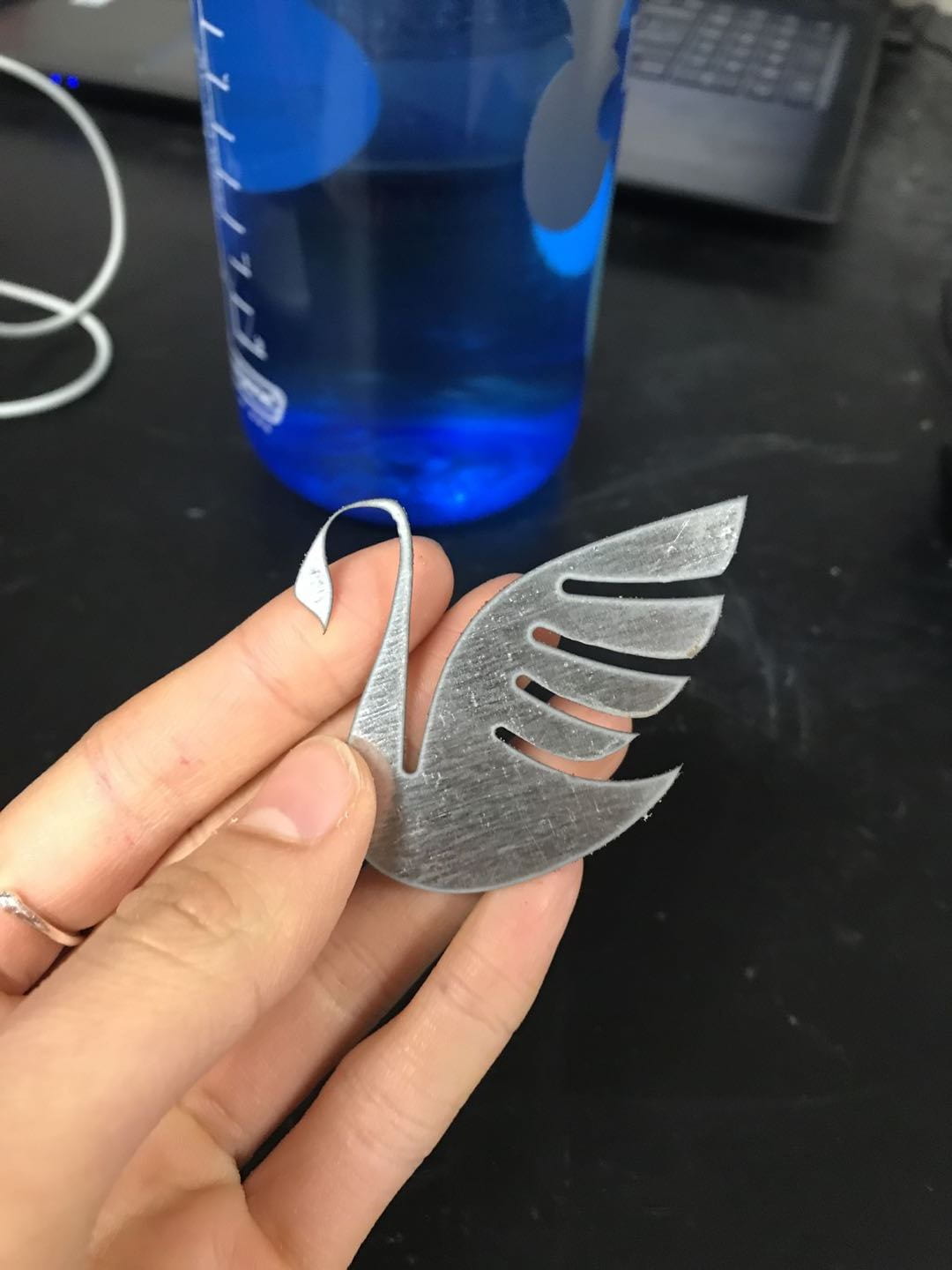
One of the criteria for this project is to include two metal pieces, one made with the plasma cutter and the other with the water jet. Here is a comparison in terms of the neatness and precision between the two. It’s not hard to guess which one I ended up using for the aesthetic purpose 😛
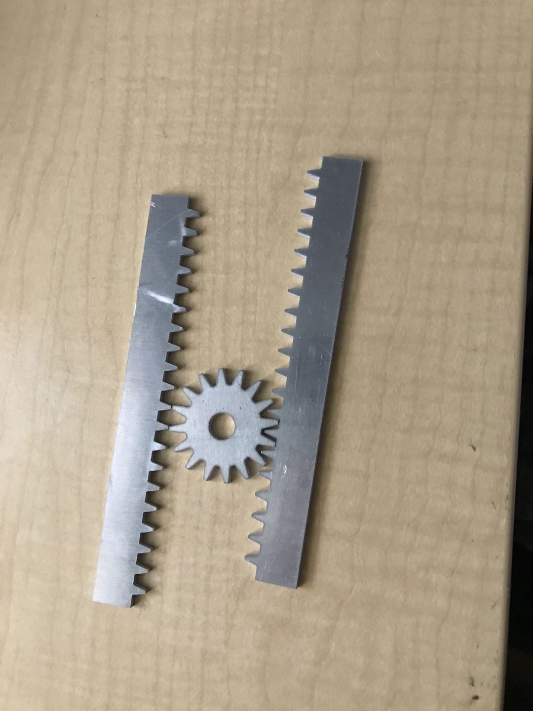
As for driving the system, initially, the user would have to twirl the central dowel from the top. I added a gear and pinion mechanism hoping to increase the ease of use. I modified a pre-existing 2D drawing for this mechanism to fit the purpose of my project and cut it with the water jet. I was lucky that the mechanism worked in the first try (whooo~). Now the question is: How do I integrate it into my project?
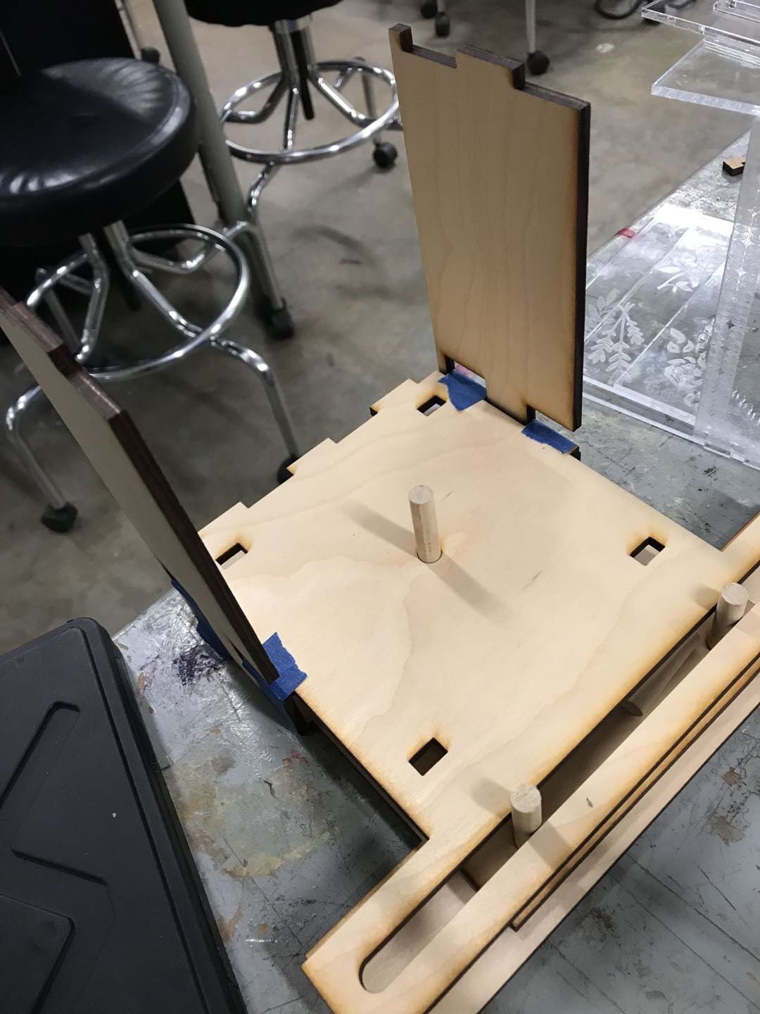
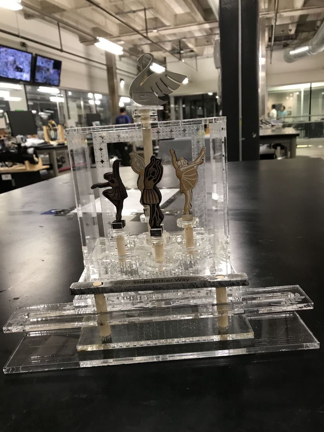
At this point, my project can basically be decomposed into 3 design blocks: (1) The elliptical planetary gear mechanism (2) The box that represents the stage, but more importantly provides support and (3) The gear and pinion mechanism from which the force enters the system.
The box presents the least constraints on the other two. The central gears of both gear mechanisms have to be fixed on the same central dowel (this is a constraint) and the motion of the pinion will be linear, across a range of space longer than the original dimensions of the box. The two obvious locations for the gear and pinion mechanism will be on top of the box or below the “floor” of the stage where the ballerinas are. The ballerinas will be at about the same level of the user’s hand and eyes if the gear and pinion mechanism is below them, otherwise, it would be a little awkward for the user to push/pull the pinion from the top of the box and try to look down at the ballerinas.
With this in mind, I added a “basement” to the box for the gear and pinion mechanism. To keep the pinion in contact with the gear, I fixed two dowels in it, whose motion is limited by the slot in the box. I built a wood prototype of this modified box and gear-pinion mechanism to make sure they will fit together before moving onto acrylic (more expensive and takes longer to cut). The first wood box did not work ideally because the pinion was not always in contact with the gear and the slot was a tad too narrow. Adjusting a couple of dimensions took care of these problems.
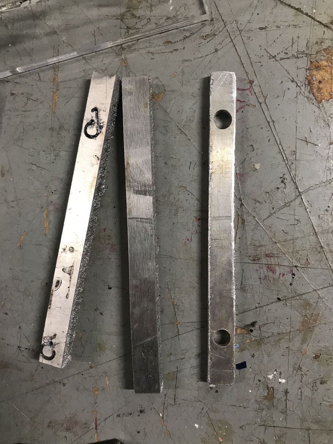
To include a functional metal component made by the plasma cutter, I made a metal arm to connect the two dowels. The uesr can now slide the metal arm to drive the system. It took three tries for the plasma cutter to get this cut right…The technical reason for the first two failed attemps? A mystery, but as the other lab techs would say: “The plasma cutter was not happy that day.”
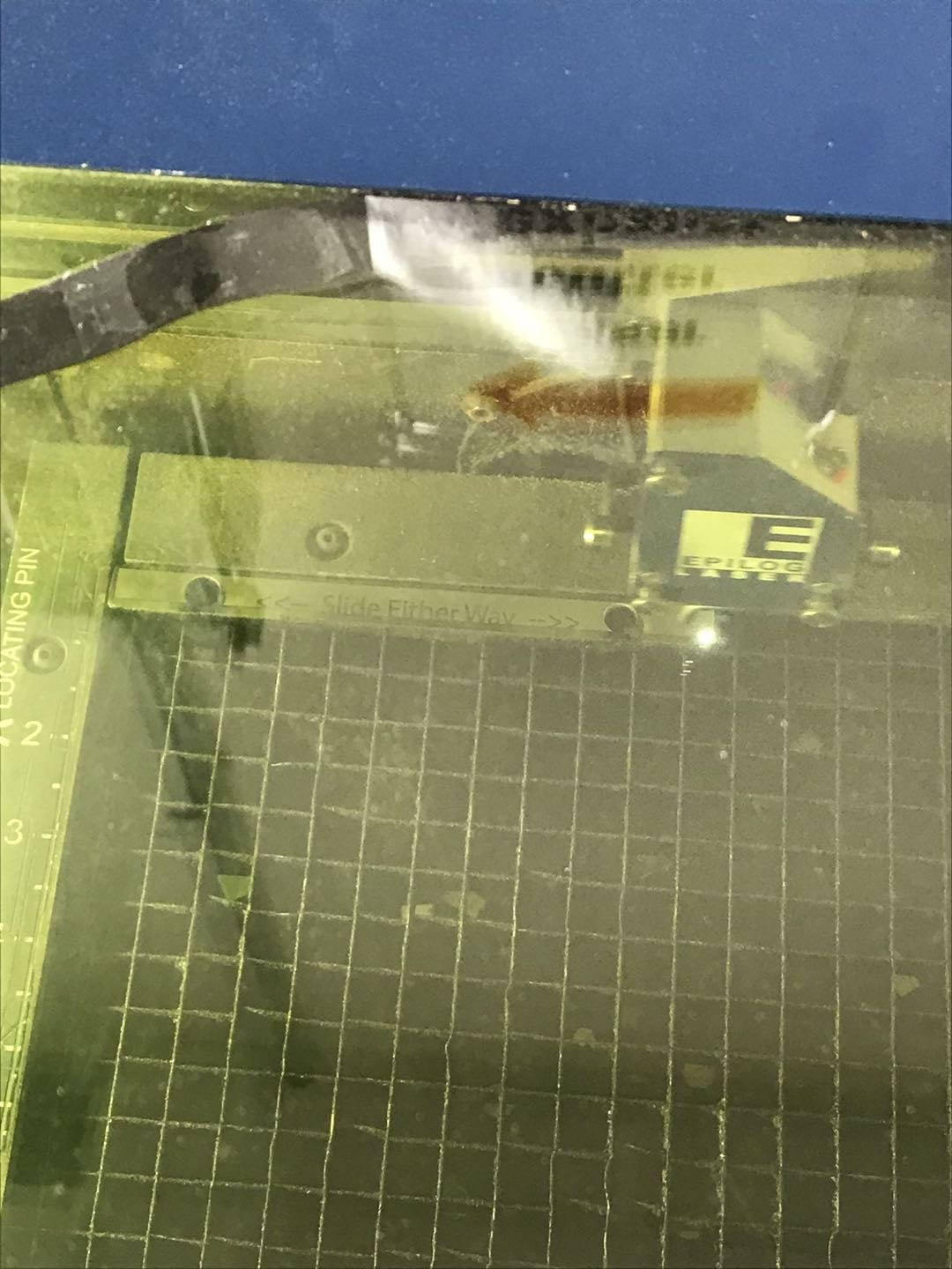
I spray painted the arm black and then etched off some paint with the laser cutter to create the simple instruction for operating the project.
Now onto the final product:
Cost estimate:
2 sheets of plywood: $5*2 = $10
3 sheets of 1/8″ acrylic: $13.88*3 = $41.64
2 sheets of 1/4″ acrylic: $25.77*2 = $51.54
Labor: If I have to put a price tag on it, fine, let’s say ~40h*$9/h = $360, but truthfully: A Velvet Tacos dinner. A week into this project, I have already lost track of the number of hours going into it (lol shrug). Despite the many many hours it took, the amount of freedom I had to be creative and adventurous in this project made most of those hours not feel like work but rather experimenting and playing at the oedk. After completing this project, I treated myself to some delicious Velvet Tacos with Audrey (yes we miss her). If time permits, will I do this again for the fun and the food? Yes. So let’s say that’s how much the labor would cost.
Spray paint:$3.98
Wood Glue: $2.78
Acrylic Glue: $14.76
Total: $487.7 OR $127.7 + some tacos
A few other things at the end:
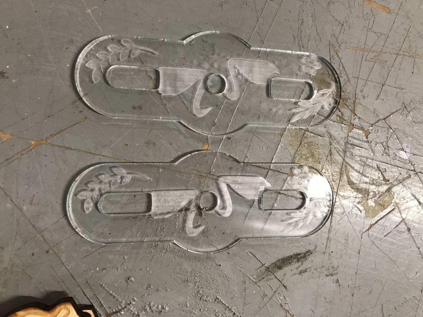
- How the ballerinas were made: For each ballerina, I made two cuts identical in size that are mirror image of each other, and then glued them together so there is etching on both sides. The wood was spray painted before the eatching and cutting so there is a larger color contrast.
- The alignment of the gears and the “stage”: I cut out two extra holes on the gears to put dowels through so they are lined up correctly for gluing. As for the “stage”, this was done with the tabs.
- I think it is fair for me having included an Easter Egg dedicated to my suitemates who gave me the inspiration of the ballerina in the first place as well as so much support along the way (eg. sending a search party for me to the OEDK, with Domino’s, when it was past midnight, then they perfectly missed me leaving just a few mins prior taking a different path back to the dorm, almost had to send a search party for the search party) .
- “Nick and I think she looks like an Anastasia.” — Anna Jorgensen. In honor of all the helpful advice I received from Anna and Nick, the swan on the top will be named Anastasia.
