Hi everyone! This is Sarah and Madison and we’re here to tell you about the process we took to complete our midterm project. Our idea consists of 3 vertical levels, a combination of gears, duck/alligator figures for aesthetics, and a metal hand-crank to make the whole mechanical model move; our thoughts were that the alligator would move on the second level with the 3 ducks spinning around the third level simulating the ducks being on the upper surface of the water and the alligator down below. In this blog you’ll be able to see our overall process in making our mechanical model come to life, the obstacles we ran into along the way, and how we got past those obstacles to get to a final working model.
Gate 1: Idea & Sketches
With a good idea of what we wanted to accomplish, we set out to create conceptual drawings of what we were thinking as well as general dimensions for the levels. Our initial design with the three levels can be seen below (without much dimensioning) and includes the 4 gears we were planning on using at the time (ended up using 7 total). The three levels in the image below were more to give us an idea of how the design would work rather than the actual size. The main points to note are the smaller circle for the accessory gear on level 1 as well as the smaller circle on level 3. Our rationale for making these smaller were that we knew the accessory gear didn’t need to be large as it was purely functional and knew we wanted to allow the alligator to be seen from the top level.

A level-by-level breakdown can be seen in the image below in order to better understand how each level works as well as the footprint of the levels underneath. As you can see, level 1 (lowest level) includes the 2 gears that begin the overall motion, level 2 (middle level) includes the gear where the alligator will rotate, and level 3 (highest level) includes a turntable where the 3 ducks will spin. The dotted lines represent the footprint of the levels underneath.

Gate 2: Low-Fidelity Design
With our idea approved and theoretically functional, we moved on to finalizing our Adobe Illustrator files, laser cutting with cardboard, and constructing our mechanical model in a low-fidelity prototype.
After figuring out how to use the geargenerator.com website and playing with various teeth numbers and pitch diameters, we put together a variety of different Illustrator files that we could print separately on the Epilog M2 Laser Cutter. One thing we didn’t notice very early, but came to realize when we printed was that our design was very large! Thankfully, we cut our design out in cardboard early on and could scale our files down later on when working with actual plywood. A few of our original Illustrator files can be seen below; this does not include all of the shapes needed as they were spread out over many files due to sizing on the 40×28 bed. The gears shown below are also not labeled which is something we started doing later on to make sure we had all of the parts needed.


When cutting the cardboard with the laser cutter, we did have to adjust a few of the settings as it didn’t cut all the way through the first time. Since we didn’t take the cardboard out of the bed after the first print, we were actually able to redo the “Job” and adjust the settings to a higher power and lower speed. We were fortunate to be able to be able to retrace our original cut and had no problems with this.
Cutting with the cardboard also allowed us to better understand proportions of the design as a whole as well as the duck and alligator figures we’d be adding. We ended up scaling the duck down to 1/3rd of its original size at this time, still with the larger design we were originally planning to implement.


In order to construct our design, we used a combination of cardboard, plastic straws, and packing tape. This low-fidelity prototype allowed us to conceptualize our design as well as the scale we’d like to make it at. When working with the gears, we did note that we’d need to make sure the center gears are perfectly in the center for our final model as the gears didn’t work perfectly if they weren’t lined up at all times. In addition, another group gave us a great idea of creating 3 smaller gears for level 2 (where the alligator would spin around) and even if only one of the the gears has an alligator, the others would allow the central gear to stay centered and aligned. The first image below shows our larger scale mechanical model while the second includes both the larger and smaller scale (0.5x) ones. We both think this was a good idea in the long run because if (and when) we inevitably messed up on laser cutting our wood pieces, we wouldn’t be wasting as much wood with the smaller size.

Large scale model only
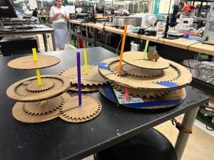
Large and small scale models
Another component we added after talking to the teaching team was the middle gear on level 2 and the three smaller circling gears; this takes the form of a track where one of the gears would have the alligator on top and the other two gears would help stabilize the gear set as a whole.
Lastly, our idea for the crank was to use the water jet cutter to create a hand crank in the shape of a wave. We thought this would fit with our theme and give a nice visual appeal as well.
Gate 3: Medium-Fidelity Prototype
Our medium-fidelity prototype consisted of the smaller model (scaled down by 1/2) from above, but with the plywood to make sure the gears would be functional and were the correct distances away from one another for smooth movement.

This step was one of the most challenging and where we had to problem solve a bit more in terms of how our model would functionally move. We’ve listed some of the key alterations/additions we needed to make to our low-fidelity prototype to make it functional and add movement.
- Addition of center holes to each level to allow for dowels and bearings
- We originally laser cut our wood without the central holes and, in hindsight, definitely would have laser cut those along with the outline of each shape. Since we didn’t do this at the start, we were able to use the drill press to make 3/8″ holes for platforms/gears that would be glued to the dowels, but needed to recut the platforms that would press-fit with the bearings.

- Addition of three bearings (two on level 1 and one on level 2)
- The bearings were very useful in allowing us to connect the dowel to various platforms, but allow some of the platforms/gears to spin while others would stay stationary. The bearings were used for the two platforms at the bottom in order to keep a static base as well as level 2 in order to allow for movement of the gears, but no movement of the platform itself.
- Decreasing diameter of level 3
- The diameter of level 3 was further decreased when we were able to see the size of the alligator and where the smaller gears would place it with respect to the ducks. We wanted the alligator to peak out of level 2 so adjusted the diameter to allow for this.
- Using duck/alligator templates as starting points, but decided not to construct the entire fit-press structure for each
- Originally, we were going to use templates for the ducks and alligator tocslot multiple pieces together to make a 3D figure, but there was a problem during testing. We realized we’d need to make the ducks and alligator by hand since the template we found was made for thinner wood versus what was available to us at the OEDK. Our plan then morphed into taking the basic cut of the duck/alligator, cutting multiple of the same, glueing them together, and sanding the sides to create a more realistic figure.
In addition to the laser cutting and various sizing of holes we needed to adjust our design to, we used Adobe Illustrator to create a wave, then the water jet cutter to cut a hand crank for our mechanical model, and finally drilled a 3/8″ hole in the handle with the assistance of Joe. The Illustrator file can be seen below.


Our Final Product!
To finish off our mechanical model, we had already proven that functionality of the gears were possible so our main goal was constructing everything to be tight-fit/stable and making the entire model aesthetically pleasing. There were a few key components to increasing the stability of our design including:
- Whittling down our dowels to make them fit tightly into each of the three bearings
- Drilling five holes on the outer edge of level 1 to allow the dowels to fit tightly and stabilize the connection between levels 1 and 2
- Created spacers to raise the gears and allow for smoother movement
- Drilled a hole in the center dowel to create a functional peg; this was necessary in order to include a spacer on level 2 as the spacer’s diameter is significantly smaller than that of the dowel
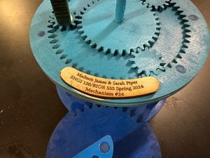
With our model stable and functional, we were able to move on to the aesthetics of our design as a whole. With our idea stemming from the alligator/duck interaction, we decided to create a pond-looking structure through the use of spray paint, vinyl, and lots of sanding down of parts! We started by sanding all three levels with the orbital sander in order to get a smooth finish once the spray paint was applied. After sanding, we decided to spray paint the levels with the following colors:
- Level 1 = Dark Blue (deeper water in the pond)
- Level 2 = Light Blue (shallower water in the pond)
- Level 3 = Light Blue (shallower water in the pond)
- Ducks/Alligator = Yellow/Green, respectively

After putting all the levels together, we felt our model was a good representation of the depths of a pond in which an alligator would lurk as well as the shallower surface waters where the ducks would swim around. Lastly, our functional water-jet cut crank was covered with a dark blue vinyl to match the first level that it is on and simulate a wave.

Overall, this project took a lot of time and coordinating between the two of us to make sure we could get a functional model completed on time, but both of us felt like we were extremely efficient when we were working together and made the most of the time we had. We felt we were able to present on our model at each gate with ease and finished a few days early as well! As challenging as the project was, we both learned a lot about different prototyping techniques and the various machines in the OEDK which will be extremely helpful for the rest of this class and in years to come!
Lastly, we made sure to clean our table each time we left the OEDK and leave it better than we found it!
Cost Breakdown
| Cost Type | Cost | Price | Source | Quantity | Total |
| Materials | Cardboard | $2/box | Packaging Hero | 4 | $8 |
| ⅛”x4ftx8ft Plywood | $16.98/sheet | Home Depot | 2 sheets | $33.96 | |
| Wooden dowels | $1.07/48 inch dowel | Home Depot | 2 dowels | $2.14 | |
| Ball Bearings | $3.82 | Grainger | 1 | $3.82 | |
| 1x2x8 inch Aluminum | $21.86 | Amazon.com | ½ inch | $1.36 | |
| 13×3 feet Blue Vinyl | $9.99/roll | Michaels | 1 foot strip | $0.25 | |
| Sand Paper | $2.50/5-pack | Home Depot | 1 sheet | $0.50 | |
| Labor | Prototyping Engineer (You!) | $20/hour | ZipRecruiter.com | 22 hours*2 engineers | $880 |
| Overhead | Facility Cost (Machine Time) | $90/31 days | TXRX Labs | 1 month | $90 |
| Quality Control | $40/hour | Glassdoor.com | 2 hours | $80 | |
| TOTAL | $1,100.03 | ||||
Presentation Link (with video of working model)
