
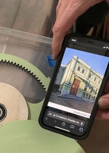
The automata from Hugo, based on “Draughtsman-Writer” by Henri Maillardet
I. Prologue (Goal Setting):
From our first brainstorming meeting, Grant wanted an automaton hand that would write, based on the ideal of Maillardet’s famous device. He was eager to design a three-axis cam system to accomplish this motion.
In general, AJ had more qualitative contributions like, “why would a user want to actually engage with our device, rather than simply watch someone else use it? how can we make it a unique and different experience for each audience?” However, they did contribute the idea for “setting the stage” for user experience via a curtain that opens and closes using opposite rotation.
II. Chekhov’s Pun: The name and the Eastern-European influences…
We decided early that writing is complicated, and for the timeline and scope of this project, a checkmark would be fancy enough. Each user could customize the interaction by supplying their own item to ceremoniously check off. The sound of “check off” is similar to “Chekhov,” and that coincidence guided us forward. We were both already familiar with the literary significance of the expression “Chekhov’s gun,” so we followed its maxim:
“Remove everything that has no relevance to the story. If you say in the first act that there is a [pistol] hanging on the wall, in the second or third act it absolutely must go off. If it’s not going to be fired, it shouldn’t be hanging there.”
So we thought carefully at each next point about what was essential to the function and theme. The box would literally be a stage, and the curtain opening would represent “the first act” (by the user). The finishing steps (color choices for paint, vinyl cut or laser etched logos, and typeface/language) would all hearken back to the historic eponymous Chekhov Moscow Art Theatre building.
III. We like to move it, move it. 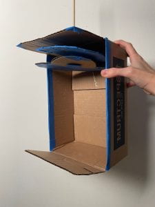
We like two movements…
We had initially considered a “three-act” play. After the curtain opening, this version would have included a graphite block swiping across a laser-cut raised square under the paper to create a check-box. Then, in the last act, a crank would turn to make check-mark happen. However, we decided that the middle step wasn’t essential to the plot and omitted it.
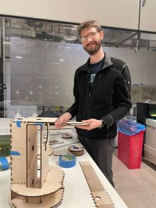
The low-fidelity arm.
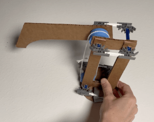
For Act one, AJ’s mockup was as low-fi as they come–mangled cardboard, painter’s tape, a chopstick–but it got the idea across to Grant enough to begin the SolidWorks CAD. For the class Gate 2 check-in, Grant whipped up a much more functional drawing arm prototype using a pulley, cardboard linkages, and K’nex plastic toys. The design progressed almost entirely in SolidWorks. Grant consulted “the Bible” (Machinery’s Handbook) where he spent far longer than necessary learning about the details of cams: how they should be made, how to keep machines built with them from tearing themselves apart, and most importantly, how to turn a relatively complex motion path into a minimal number of cams. He also started to become aware at this point that the tolerances, and most importantly rigidity, of the materials was of utmost importance. (Foreshadowing!)
IV. Aaaand, ACTION!
Efficient use of materials!
 We found a nice workflow with Grant extracting the individual faces of each part (40+ if anyone was counting), and exporting them as .DXF files. AJ opened the files and arranged them into one document that we could load into the laser cutter. Great idea to save time and materials! Except… we next realized that our wood was too big in one dimension for the cut bed. So we had to rearrange the whole set of parts. We managed to keep our scrap to a minimum, though!
< Queue the musical montage scene of cutting, assembling, and running about. Ideally have four or five body doubles of both AJ and Grant, with the inevitable surprise collision where someone meets themself. >
 A good bit of time was spent carefully assembling, aligning, disassembling, painting, then reassembling everything. Thankfully Grant designs things from the standpoint of production, so despite all of the interlocking finger joints, shafts, and cams, they all fit together in the very specific order of assembly on the first go-’round.
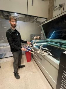
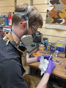 We decided that the aluminum parts for the actual drawing arm would work best glued together, so Grant used some JB-Weld to attach them. In addition to modeling proper behavior for students, he’s also wearing full PPE because he is extremely allergic to most 2-part epoxy resins. Don’t do this to yourselves, kids!
V. Descent into madness, or Design Deficiencies
It is at this point in our play that the protagonists find that the mechanism that works very well in CAD, and in reality when tested individually, may not function quite as well in their final form.
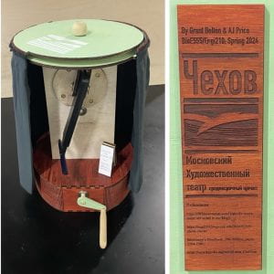
The final prototype dis-play!
Despite having designed in allowances for almost every bearing surface to be either actual bearings, or covered in low-friction HDPE tape, the friction of all three cams combined was greater than the frame itself could handle, so the structure would warp, the timing belt would cog out, and the overall main movement isn’t functional.
AJ’s mechanism for opening the curtains does work quite cleanly, though! A modified not-quite planetary gear mechanism with different gear modules for inner and outer rings allows for equal motion of both rings in opposite directions. We chose to ultimately drive that action from the top for simplicity, but there is clearance to extend the shaft of the planet gears down to connect with the main drive crank if we chose to do so in future iterations.
VI. Epilogue, or what should happen to make it more than a cautionary tale
Simultaneous multi-axis cam systems are hard–we knew that going in, and chose it because it was going to be a significant challenge. The materials we used for the cam assembly did not meet the requirements for the design. Adding a cam follower with a secondary linkage to the arm would reduce some of the flexion, but most importantly the cam followers would best be actual rotating followers: likely just small ball bearings. Beyond that, making the cams out of a lower-friction material like leaded brass (or the modern equivalent, acetal) and the frame and shafts of steel or aluminum would give the system enough rigidity to have the followers follow rather than deflecting.
Midterm Mechanism Costs
(done by AJ! They absolutely do this for every project in their daily work…)
| Cost Type | Cost | Price | Source | Quantity | Total |
| Materials | ⅛” Aluminum, cut | $25 | SendCutSend | 2 | $25.00 |
| Adhesives (JB Weld) | $7.68 | The Home Depot | 1 | $12.65 | |
| Adhesives (Gorilla Wood Glue) | $4.97 | The Home Depot | 1 | ||
| Fabric (Green Polyester, 1 yard) | $3.99 | https://www.joann.com/symphony-broadcloth-solid-quilt-fabric/517417.html | 1 | $3.99 | |
| Wood (5mm underlayment) | $25.78 | Home Depot | 1 sheet | $25.78 | |
| Paint (Liquitex Softbody Acrylic) | $23.09 | https://www.texasart.com/category/150/acrylics.html | 1 set | $23.09 | |
| Paint (Liquitex Acrlyic Medium) | $9.30 | https://www.texasart.com/category/150/acrylics.html | 2 kinds (matte and satin) | $18.60 | |
| Labor | Artist | $20/hr | Indeed | 20 hr | $400 |
| Prototyping Engineer | $60/hr | OoI rate | 20 hr | $1200 | |
| Overhead | Facility Cost (Makerspace Subscription) | $50/month | TXRX | 1 month | $50 |
| Quality Control | $17/hr | Indeed | .25 hr | $4.25 |
First article total: $1763.36
507 Movements – Mechanisms used in this project:
5, 34, 55, 96, 97, 149
Simple pulley system with tensioner, 5
Planetary Gear System analogy, 55
Linkages attached to cams, 149
