Midterm – Movements #113 and #276
Introduction
Before I begin, I would like to say that this is probably the single largest quantity of work (in terms of both hours and effort) that I have ever put into a midterm. That said, I have never before enjoyed a midterm so much, and I benefited from every moment I was engaged in the process!
Given the complicated and long nature of this project, and the subsequently extensive blog post below, I will highlight the organization of this document for the reader’s benefit: First I will discuss my Illustrator drawings of my movements, and any challenges faced therein. I will then discuss my low fidelity prototyping techniques and show my mid-process product. Following, I will discuss how I turned this prototype into a final product, at which point I will end by discussing how I turned individual components and the entire product into something presentable and (in my opinion) appealing to the eyes. I will then conclude with any overarching takeaways from the experience. I want to emphasize that this organization is not linear with respect to time; I frequently went back and forth between drawing and prototyping as I realized that different changes needed to be made or new parts had to be constructed. This will be detailed section by section.
2d Drawings
Process number one involved producing drawings of my chosen mechanical movement. Luckily for me, I had invested a significant amount of time on the previous homework, ensuring that my lines were as precise as possible, a process outlined in a previous blog post. So, I began with good outlines of both my three leaf gear element and the shaft/lugs that ride on its curve. This is seen below:
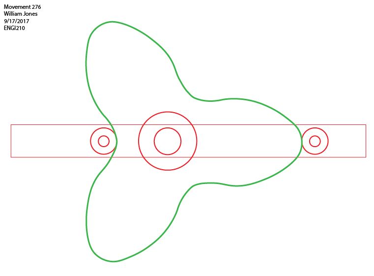
Of course, this particular drawing required many, many changes over the course of the midterm, each of which required its own thought, prototyping, testing, and revision. In no particular order, they are as follows: a slot in the shaft for the center pin to ride in, a pin to join the rack (added later) to the shaft, an increased shaft thickness to account for the slot, different diameter lug pin holes on the shaft to accommodate oedk dowels. a different center pin size for the same reason, and a different bearing outer diameter to accommodate a bearing I found in the oedk (in addition, I later had to move the bearing to be inside the stand, with the dowel rod fitting tightly to the three leaf gear.) Each and every one of these changes required me to spend a good while thinking, measuring, and drafting, and an even longer while in the laser room, cutting small shapes, testing fits, and revising accordingly. That said, this resulted in a final drawing product I was very satisfied with and that worked according to plan, which can be seen below:

Overall it looks very similar, but many hours of work went into translating from one drawing to another. In addition, during the course of building my model, I decided that having one movement was not satisfying enough, and I wanted to find a way to translate my linear translation output into oscillating rotational motion. In doing so, I would have translated steady rotation into sinusoidal rotation, a rather interested overall change. With the idea of a rack and pinion in mind, I began searching through the 507 Mechanical Movements until I found the perfect one: movement 113, which featured exactly what I needed: a simple rack and pinion.
In order to produce the illustrator drawing for this component, I followed an almost identical process as before. I took a screenshot of the motion, used image trace and the techniques I learned from the previous experiences, and produced the drawings. As before, I had to take great effort to make these parts as uniform as possible (as gear teeth require relatively good precision) and part of this process can be seen below:

Note the extremely irregular teeth on the bottom left, as compared with the tooth center top. I ended up copying the top tooth and repeating it all the way around the circle, hence the lines to guide my placement. Once this tedious process was completed for both the rack and pinion, I was able to see my final drawing:

Luckily, other than scaling, I made few modifications to this design (mostly because I plasma cut it out of steel, and rather than change the steel I just made ‘softer’ parts fit it.)
With that, I only had relatively simple drawings left to produce, including the overall support structure (which will be shown in a later section) and a couple of minor parts, shown below. Together, these comprise the drawings for my project.

Altogether, I strengthened my Adobe Illustrator skillset and further developed my competency with various tools within illustrator, including image trace, the curvature tool, and others. I definitely learned the value of saving my different files with appropriate titles (and also saving the actual files I laser cut) as with numerous parts with holes that varied by thousandths of an inch (in order to get everything to press fit) I found myself cutting parts that didn’t function several times.
Low fidelity prototyping
Step one of my design process was to create a low fidelity, ‘proof of concept’ prototype. I conducted this step only once I had drafted the movement #276, so no images are shown for low fidelity overall movements.

As can be seen I completed this process by laser cutting the shapes out of cardboard, hot gluing them together, and incorporating a bearing I found using masking tape. While this was never a singularly functional unit, it did demonstrate the feasibility of the process, and I was able to hold, see, and feel the different components of my project. This allowed me to check and ensure the consistency of my three leaf gear, and also visualize the different cuts necessary to actually fix all of these pieces together in a functional manner. In addition, I was able to learn how to laser cut cardboard, something I hadn’t done before but that was actually extremely informative. ( I learned that cardboard is stiff enough for solid medium fidelity prototypes, and can be cut extremely rapidly. Good information for future projects, to be sure.)
Having proved the concept to myself, I then moved on to more high fidelity models.
High Fidelity product
Admittedly, given that I had produced the drawings anyways, producing high fidelity prototypes/final products was nearly as easy as producing low fidelity ones. In all of the cases below, I did of course have to produce numerous copies given constant design changes, but I don’t consider it a waste as the individual pieces I cut did function as intended, and provided me with information that contributed to my final product. Below is a picture of only a fraction of the different pieces I went through. Each one has a separate story, and would take far too much time to discuss here, but if you have any questions don’t hesitate to ask!

Movement #276
In order to finalize movement 276, my original movement, I created a total prototype, which I was able to demonstrate to you in class. This consisted of a miniature base (one of the rectangles above, with four dowels) along with a purple shaft, two lugs consisting of small homemade rollers, and a clear acrylic three leaf gear with a large metal bearing. This worked much better than I thought, and I was able to realize that it was indeed feasible to drive the system via the gear. So, I switched the bearing to be lodged in the larger structure, so that a shaft passing through the bearing could be turned to operate the gear. This assembly, nearly identical to the prototype, is featured in my final product.

One of the major differences, which I will go ahead and address now, is that I replaced the direct dowel guide impingement with small bearings, intended to generally reduce overall friction. These seem to work as intended, and are featured in numerous areas of my final product, including above, as a guide for the steel rack, and as a bearing for the pinion. Sadly the internal diameters were ever so slightly larger than .25″, so I had to laser cut the finest shims I have used yet, and install them very carefully. If you look closely below, you can see how fine these shims really are.

With this, this movement was fully produced.
Movement #113
This second movement was the late addition of a rack and pinion to the total design. As discussed above, this was intended to increase the complexity of my project in a very interesting way. In order to produce this part, I took my drawing, ensured that all paths were closed, then plasma cut three nearly perfect iterations of both the rack and the pinion. Once this was completed, I bolted each set of three together using fasteners obtain from the OEDK wall supplies. The plasma cutter exhibited significant defects, one of which can be seen in the above photo, but overall produced far cleaner teeth than I was expecting! This finalized the production of this component.
Base and Other Components
The remainder of the components were designed around the interfacing of the two movements above. Below is the final product for the vertical ‘base’ to which everything attaches:

Important note: the larger bearing diameters were not cut through the base as this renders it useless (which I may or may not have done…this can be seen if you look at the back panel of my product.) In addition, note the extrusions on the bottom designed to fit into the bottom of the base:

I designed this fit to be a press fit, and it works reasonably well, minus a small gap (apparently the wood was not exactly .25″ thick, but it is close enough for my tastes.)

The various text and illustrations were added for fun, but I did go through the entire process of turning them from raw images to editable drawings in illustrator. I also did the same with the War Owl, creating my own version from an image I found online.
Putting it all together
At this point, I was able to assemble my complete product, no small feat on its own. I spent many hours hammering out small issues, such as imprecise tolerances, slight mismatches, and countless other issues. On the actual product many of these aspects are visible, such as numerous small washers that ensure pieces don’t run into one another, superglue where press fit pieces failed after repeated operation, and a small retaining bar that keeps the rack in place without falling forwards. Altogether, this was a very labor intensive process, with lots of sanding, pressing, assembling and disassembling, but a process that resulted in a product I am very proud of.
finishing techniques
Last but not least, there were numerous finishing techniques required to take my model from raw steel and wood to the complete model shown here.

With regards to the acrylic pieces, my technique was straightforward: I peeled the protective paper off and nothing more.
With regards to the wood pieces, I was a little more refined: I lovingly coated every piece with two coats of linseed oil, waiting for it to dry and sanding lightly between the two coats. This certainly served to bring out the natural color of the wood, which was much nicer than I was expecting from plywood. I applied the linseed to every exposed surface, including the wooden dowels and the War Owl.
With regards to the steel pieces, I first belt sanded all of the slag and rust off in the basement. I then bolted the triplets together and sandblasted them in their entirety. Last but not least, I applied a few layers of clear coat. Honestly I was surprised by the resultant color; to me it looks like the pieces have been painted gray but I promise it was nothing more than sandblasting and clear coating.
With that, my post processing was completed, and I was able to assemble the product for the last (hopefully) time! Below, you can see it in action!
Note the relatively smooth operation. In addition, note that the clear acrylic gear continues rotating in the same direction, even as the War Owl oscillates on its path. This particular series of motion translations is quite cool in my opinion!
Conclusion
With that, my final product has been completed, and can be seen on the group table. There are many minor lessons I’m sure will come up during the classroom discussion, but overall this project served to greatly reemphasize all of the lessons of every homework assignment so far, and truly hammered home the lessons learned. I was able to avoid my mistakes of the past (I tested small shapes on each material before cutting large ones) and made new mistakes that I can again learn from (if you get too close to the edge of the plasma cutter, it makes weird errors.) Overall, I greatly enjoyed this project and process, and I look forward to sharing my lessons with the rest of the class tomorrow!
