Hello! This is Hsing-yi Chen and Paige Rennie. We are going to take you through the many, many steps that it took to make our midterm project! Our project is called a “Pianophone” because it looks like a piano but the way that it plays notes is like a xylophone.
Gate 1: Idea Generation, Sketches and Drawings
We began by looking at the 507 Movements to help us generate ideas. After talking about a couple, we decided we would use a cam as our mechanical movement. We weren’t sure then which one it would be but it ended up closest to movement 130. In our model, the cam pushes the ball end up and then the elastic band (acting like gravity in 130) pulls it back down. In 130, the cam pushes the cutting end down of the shears and then the weight of the handles lets it fall back open. The shape of our cam is also a bit different as you will see later but this was the closest movement we could find.
Rough sketches
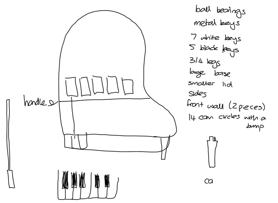
We began with some rough sketches and then used Adobe Illustrator to create our drawings. Our first version for most of the parts of the piano looked as follows.

Preliminary Drawings
Gate 2: Low-Fidelity Prototype
To prepare for cutting the piano out of cardboard we had to make all the finger joints so that the pieces could press fit together. We used the online box maker to make the piano keys and then adjusted them so that they had a long piece on the one side. We also adjusted all the of the finger joints we made ourselves for the kerf of wood. We were ready to cut out of cardboard at this stage!

Drawings used to cut the cardboard
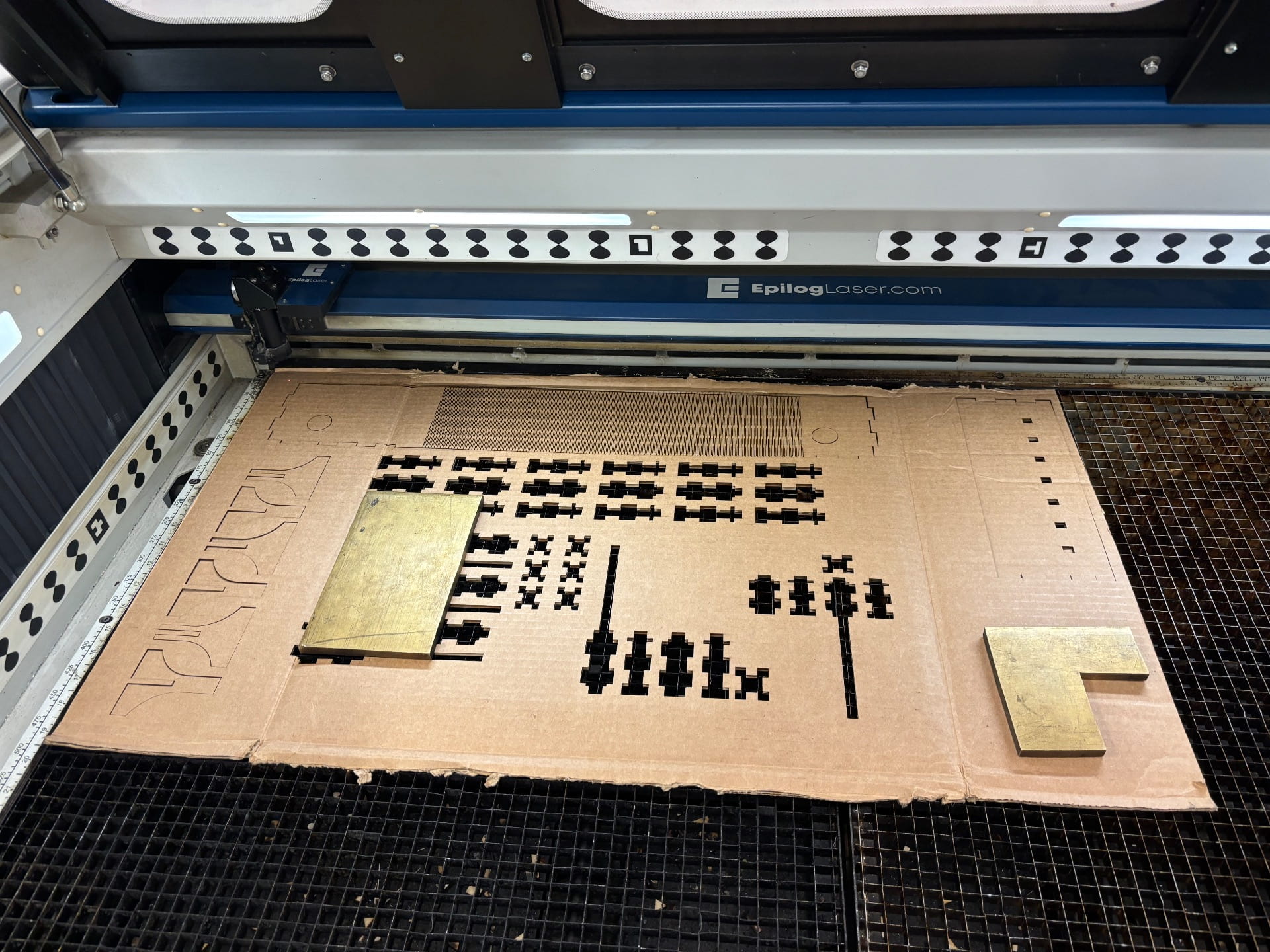
So many pieces!
This is a video showing how the cams initially worked. Our initial design had egg shaped cams that made the wooden balls hit the metal bars from below. We had issues with them hitting the keys both hard enough and quick enough that it gave a clear sound and eventually changed the shape and made the mallet hit the bars from above. Below is our final low-fidelity prototype. As you can see, we had to tape on some nuts to counterbalance the keys which we later did using an elastic band inside the piano but it worked for this stage!
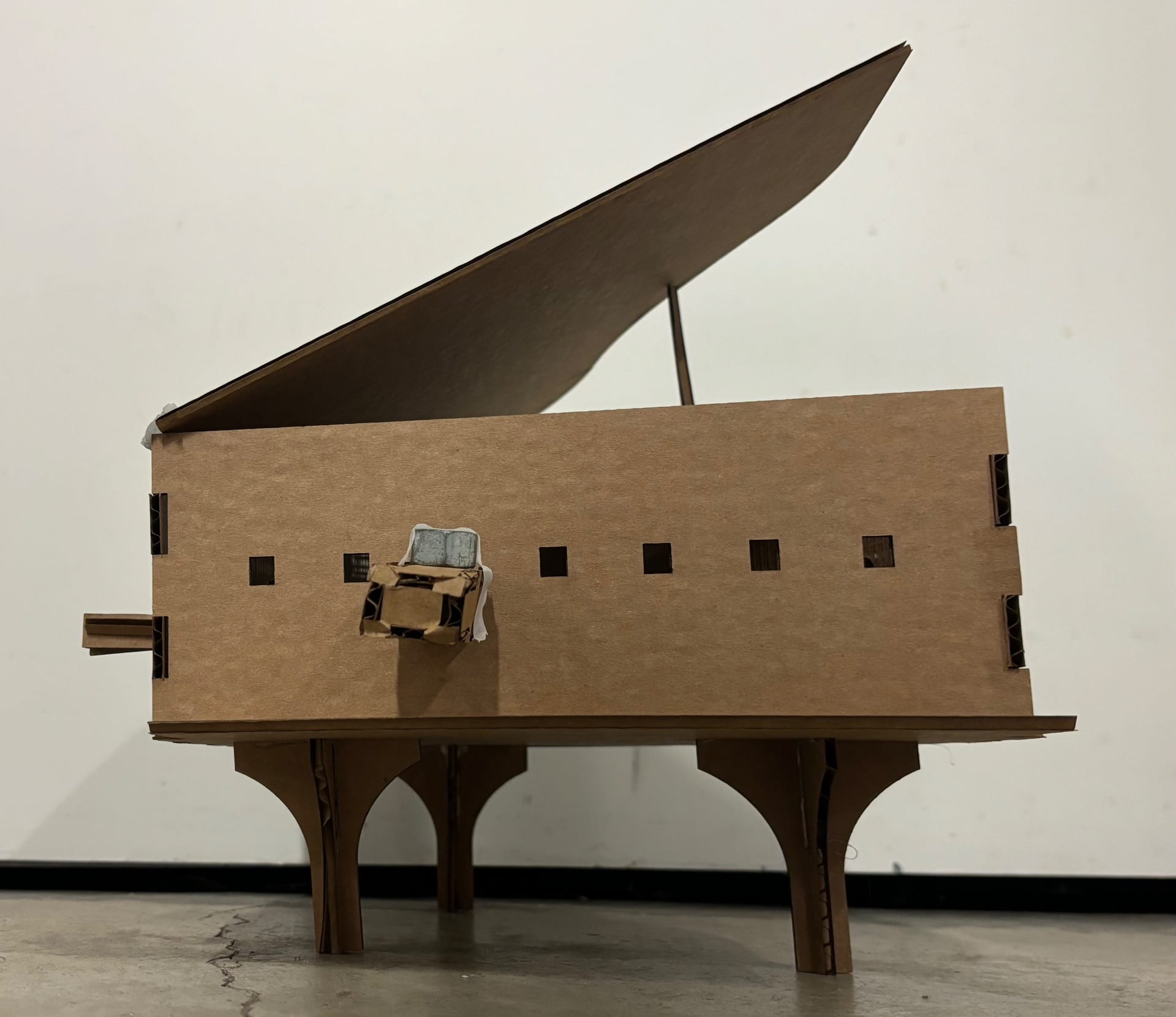
Final low-fidelity prototype
Gate 3: Mostly Functioning High-Fidelity Prototype
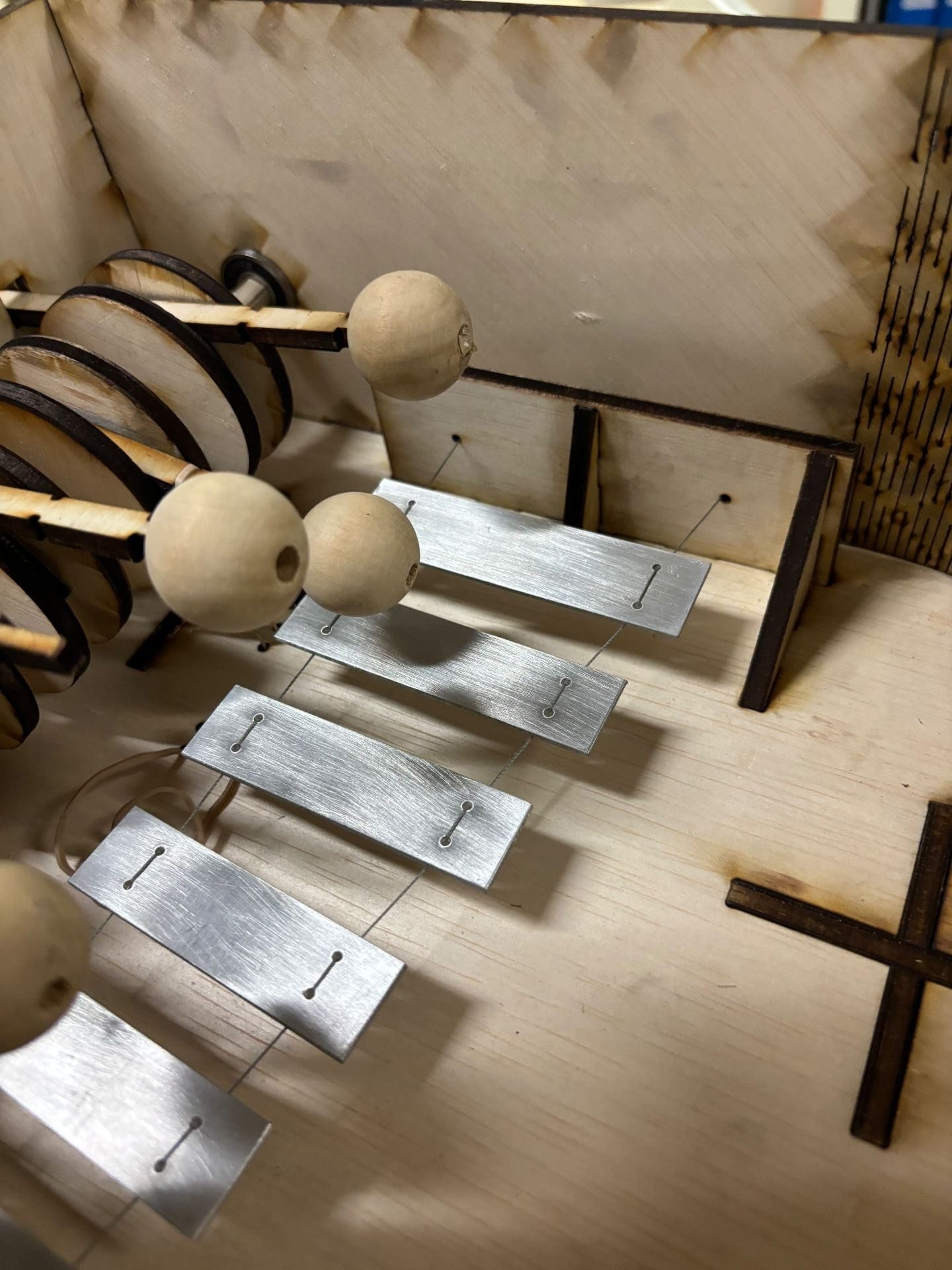
We began working on the metal bars at the end/beginning of gate 2/3 so that we would have time to figure out a plan if they did not make clear sound. Based on the size of the piano we decided that the longest key would be 8cm and after looking at past projects and their blog posts we saw that they suggested 0.5cm length differences to give different tones for each bar. We started by using the water jet cutter and drill press to cut the 8cm one to ensure that we could get a clear sound from the aluminum. We tested it by suspending it with string and hitting it with our homemade mallets made from round wooden balls we found in the OEDK attached to our keys.
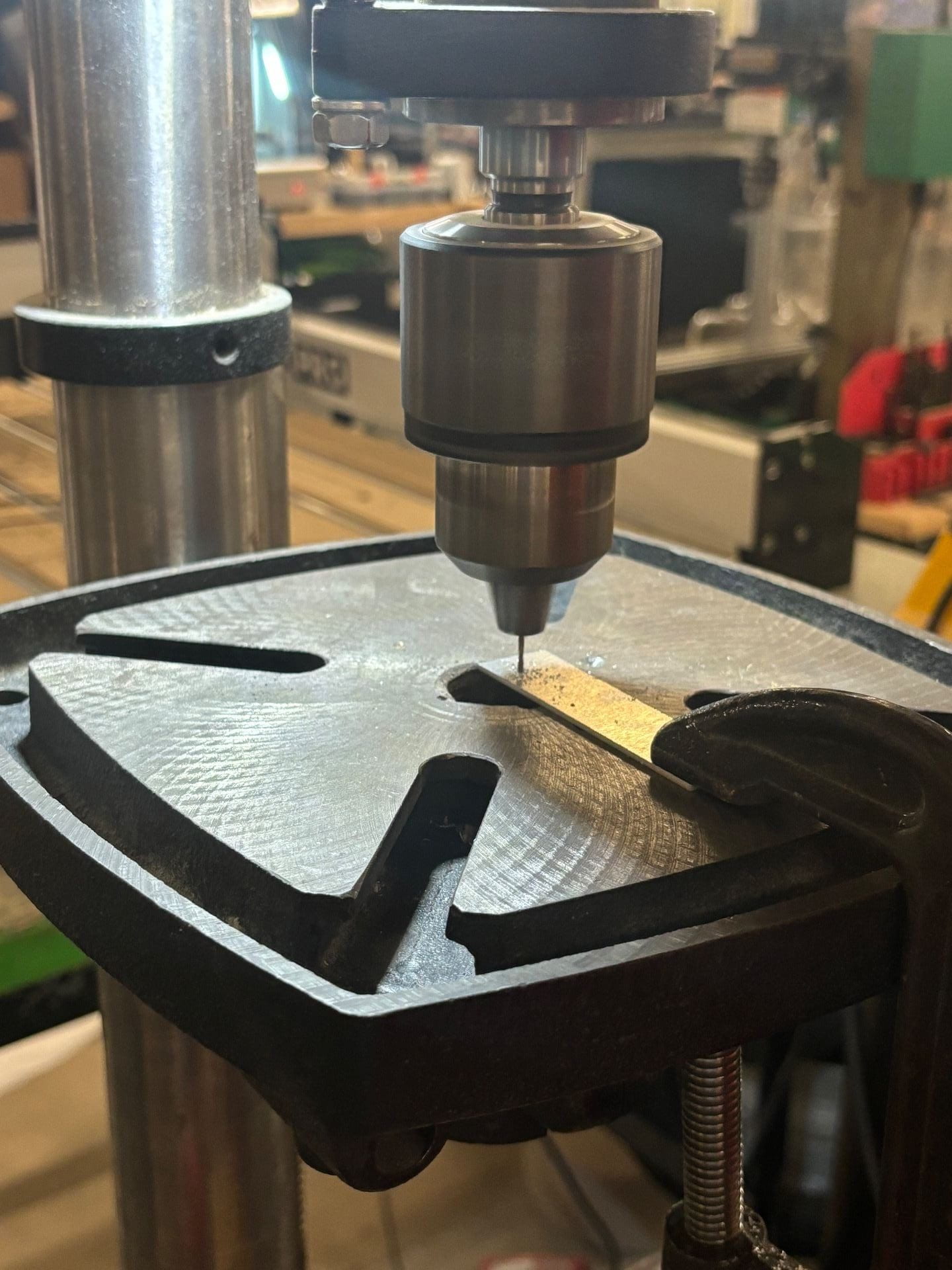
Using a drill press to cut the holes in the metal bars
Once we decided that we were happy with one key we cut the rest with lengths ranging from 5 to 8cm with 0.5cm increments. They didn’t give perfect notes and weren’t all in perfect tone increments but they gave a good sound so we decided to leave them as they were and focus on the mechanical part of the project as that was the main goal.
7 keys
We started to transition to wood as the cardboard wasn’t strong enough when we started to put more force on it like the beam across the piano and suspending the metal bars across the width of the piano. This was when we introduced the elastic band. Here, it was to try and pull the mallet away from the bar above it quicker to try to ensure clear sound (later the purpose changed).
Starting to transition to wood
After seeing the stress attaching the metal bars to the sides of the piano (and to make it look cleaner from the outside), we decided to add supports attached to the base of the piano, inside the outer wallers, with 90° pieces to add extra strength.
Testing the kerf, strength and position of the supports
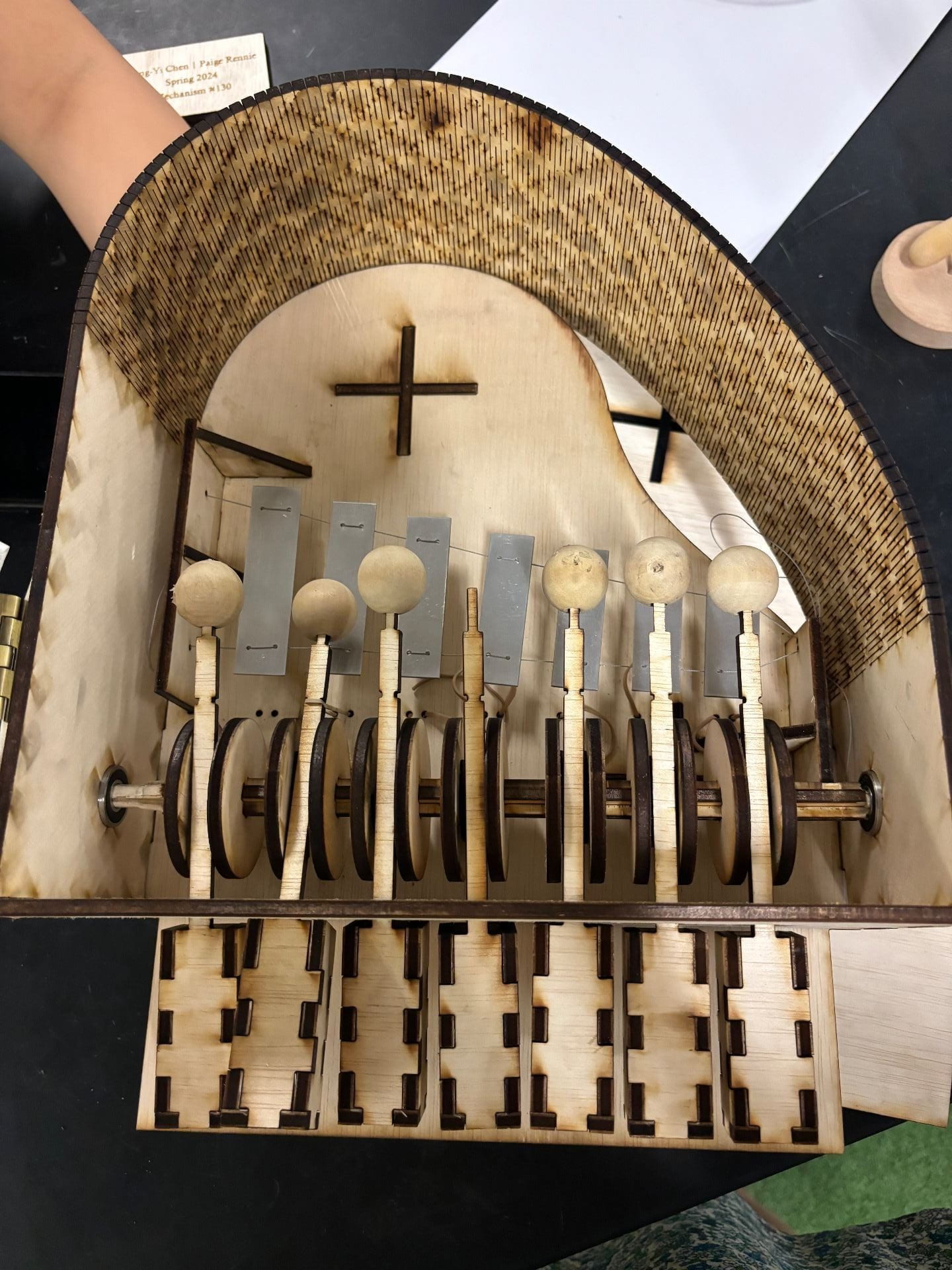
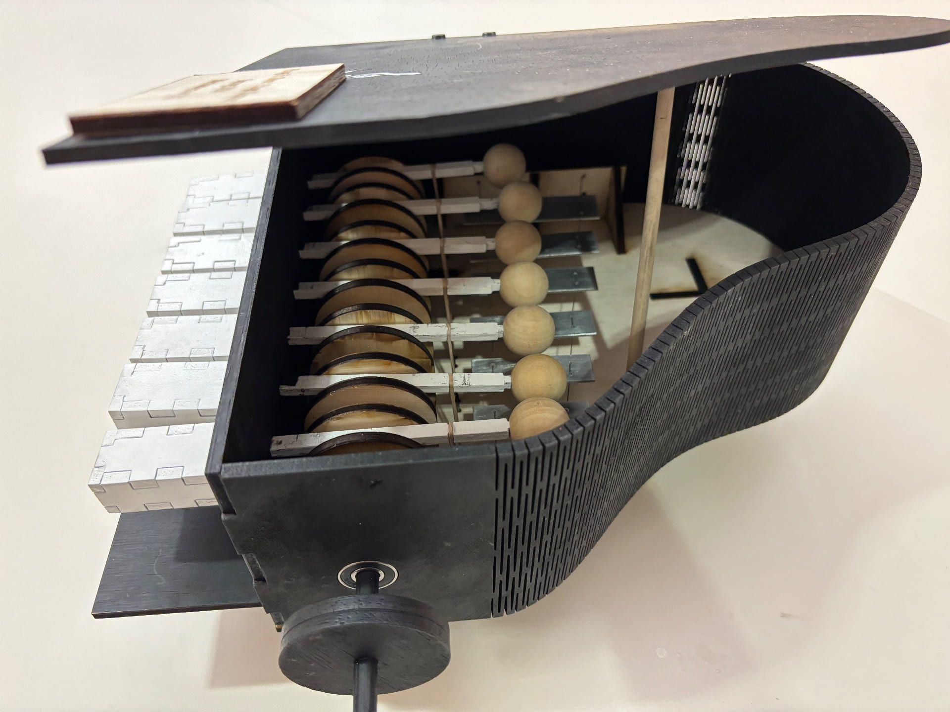
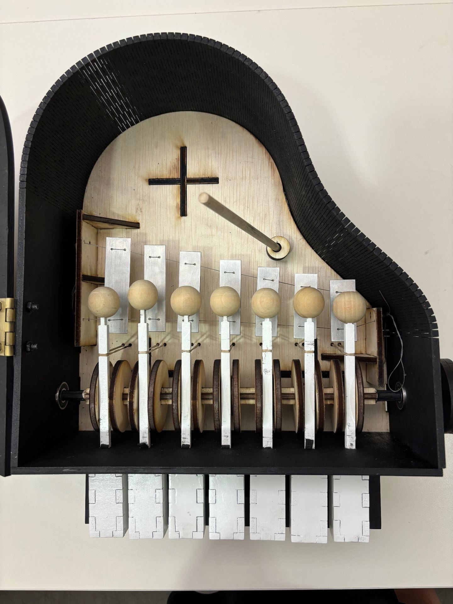
We changed our cam shape to give a more clear sound. We made them almost hemispheres with a flat side that induced a quick drop onto the bars and also because of the elastic bands. Each was 45° more rotated than the previous one so that each note would play at a different time and the plus shaped crossbeam ensured that they stayed in that position.
New cam design
Diaries of the Living Hinge
(it deserves its own subtitle as each one took at least 30 minutes to cut!)
Now came the fun. We started our many attempts to get the living hinge correct. We had cut all our other pieces at the same speed, power and frequency but the hinge was a nightmare! The first attempt didn’t cut all the way through on one side. After advice from a lab tech about the new speed we should use, the second attempt mildly incinerated the wood and was very weak.
First attempt at the living hinge in wood
To prevent more mistakes from happening we finally learnt to do small test cuts (which we should have been doing from the beginning!). We went with the speed on the right (pretty sure it was 15) and cut one more attempt that we thought would be the end.
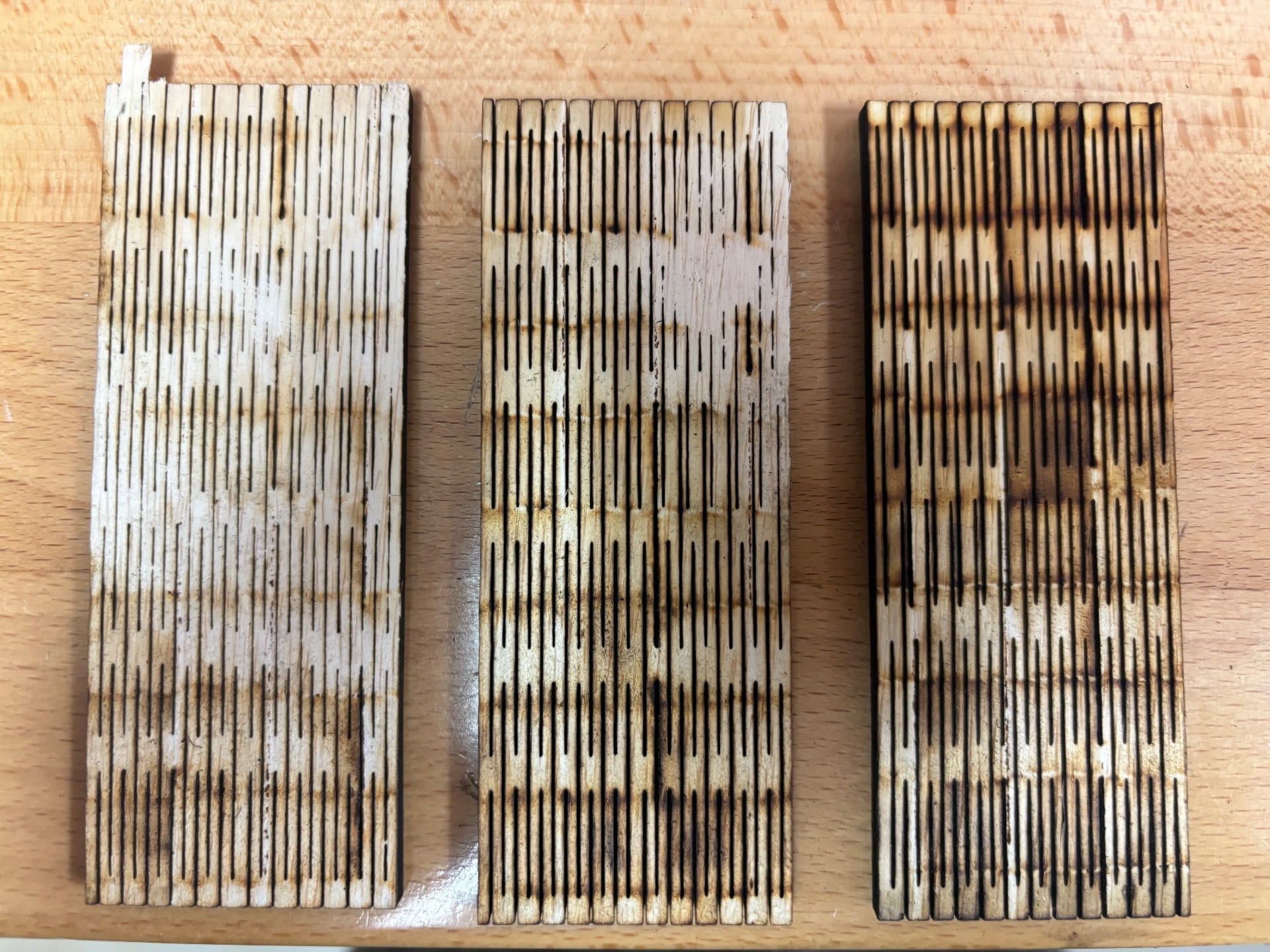
Three speed tests
But alas, there was a weak point and it broke as we took it out the laser cutter.
Broken hinge
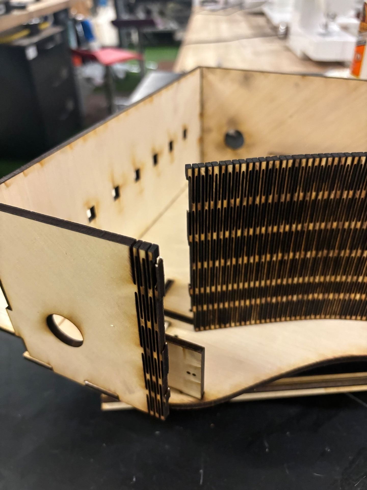
Looking closer at some of the living hinge samples in the OEDK library, we saw that they spaced the cuts further apart in the hinge making it stronger and also made it have less burning. (We also did lots of test cuts with this one…we had learnt our lesson!)
Before the final cut, we made sure that the kerf was exactly right to fit both sides of the base of the piano and did tiny test cuts to ensure it was right (we had scaled up the piano at some point to be able to fit the metal bars inside and the kerf had been affected).
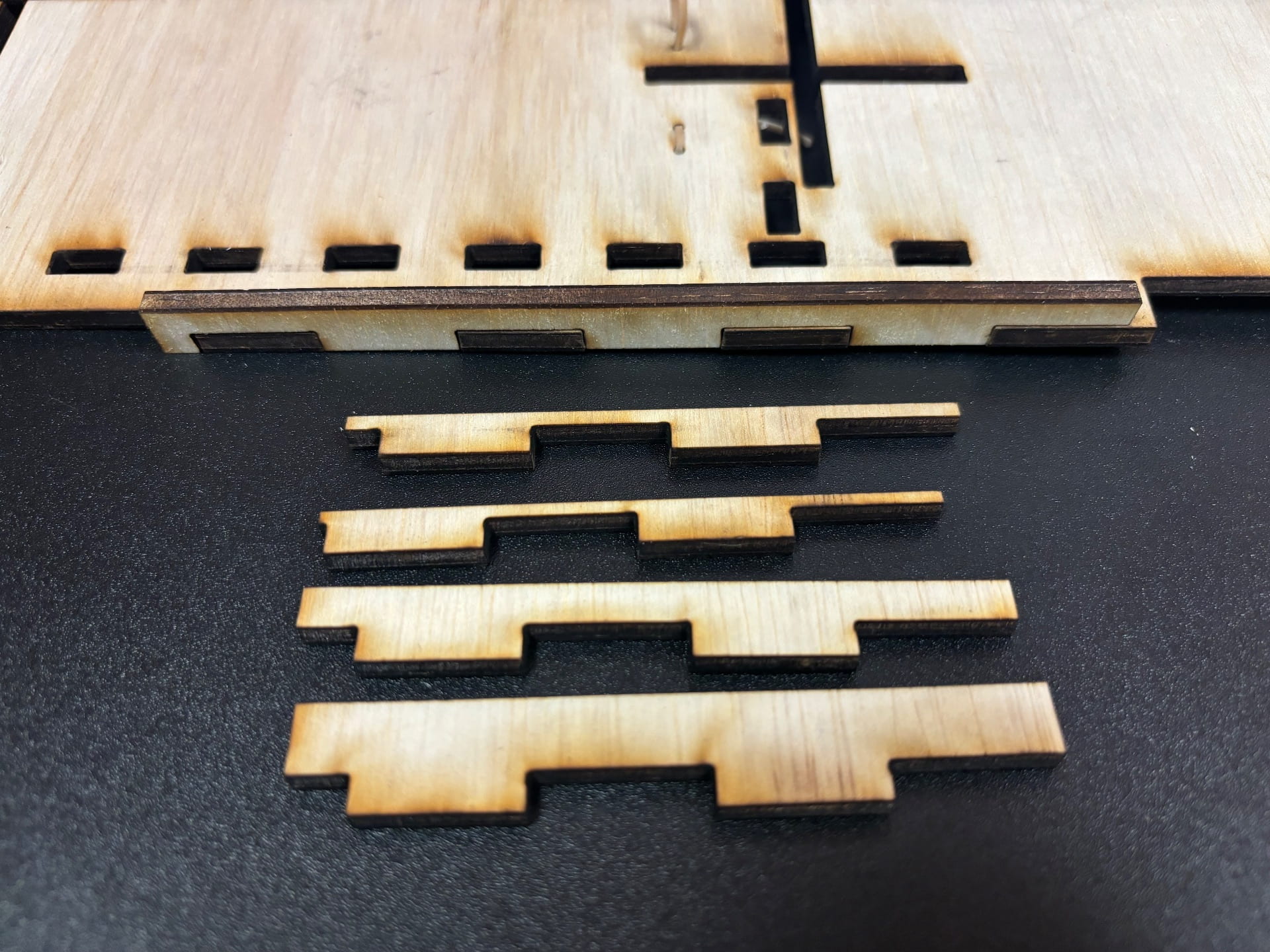
Tiny test cuts for kerf
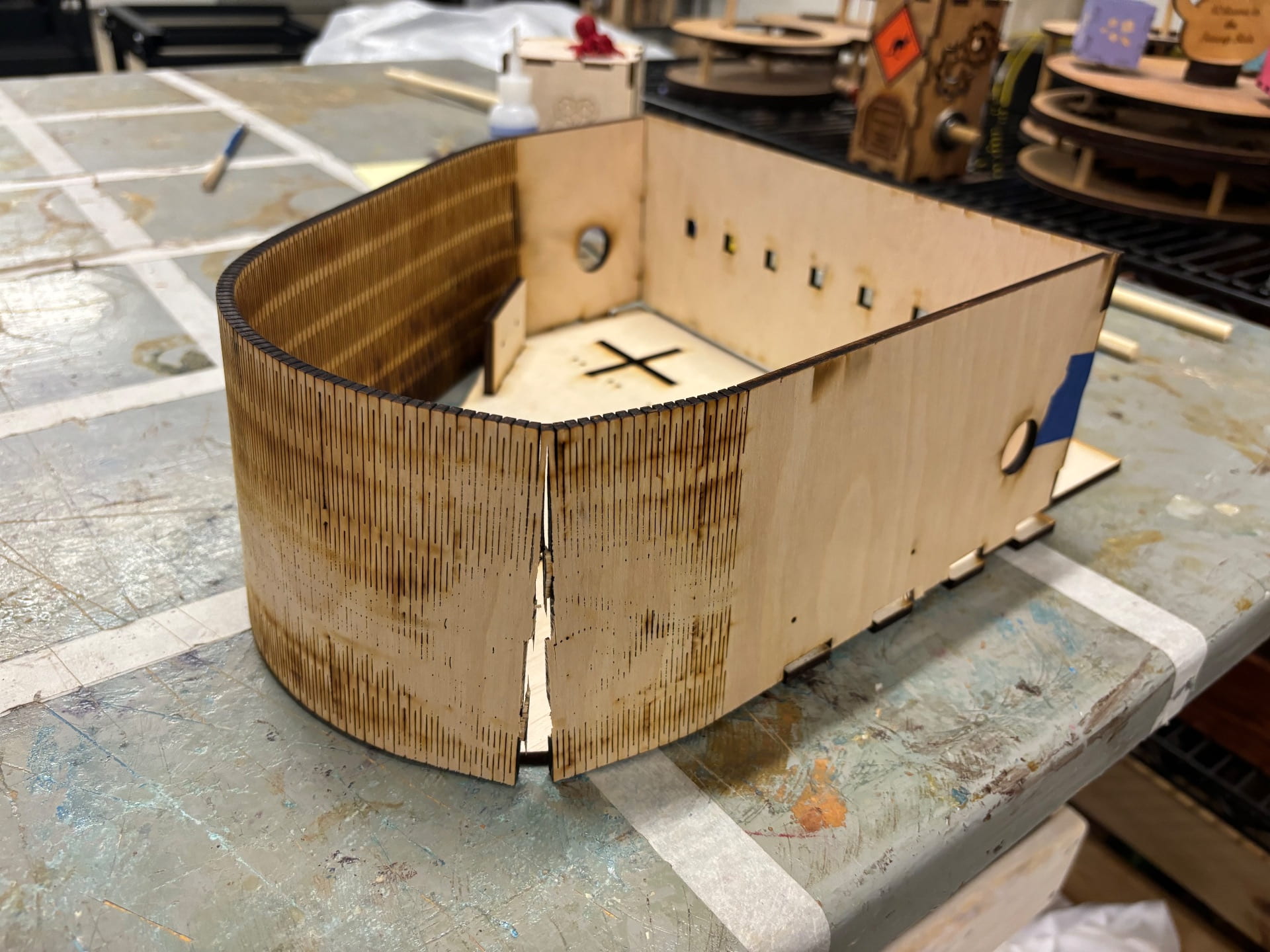
Final living hinge (finally!!)
Final Project
We started to finalize our project and put everything together. One of the issues we discovered (despite being so careful with measurements) was that the mallets didn’t hit the bars at the height that they were suspended from. To save wood, we decided to just drill new holes in the supports so that the bars would be at the right height. We also eventually added buttons behind the support to spread the force from the tension of the strings as the tension was making them cut through the soft wood.
Mallets not reaching the keys
A couple more adjustments that we made:
The crossbeam that supported the cams was not strong enough if it was turned on only one side so we lengthened it and added wooden circles on both sides to act as handles and provide more grip to be able to turn them. The crossbeam was also sanded so that it could press fit into the bearings.
One of the supports was a little too close to the crossbeam and was adding friction but that section ended up being sanded down to fit into the bearing so it was fixed easily.
Final project before post processing
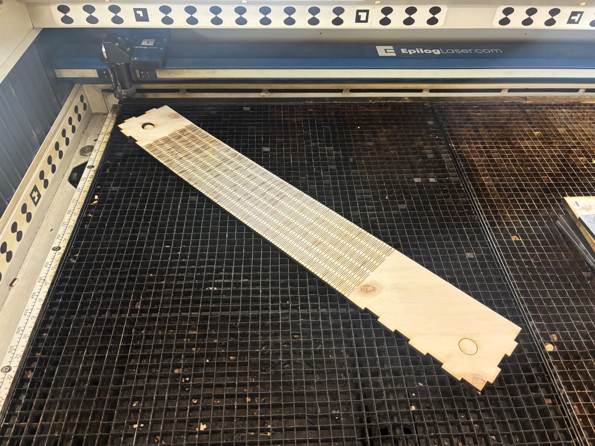
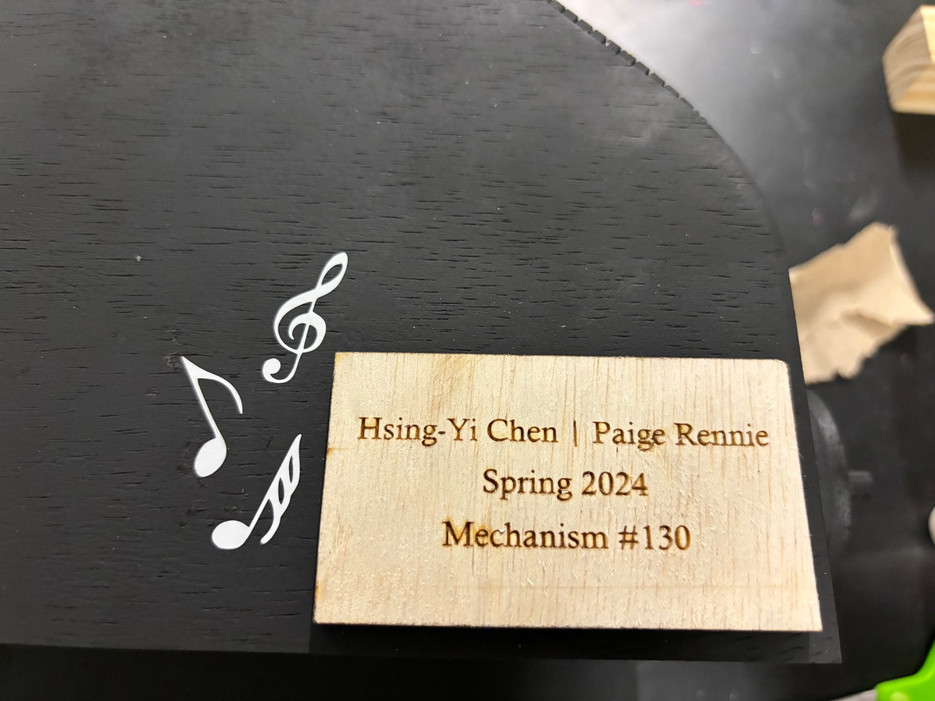
We cut our name plate with tape to prevent any laser burn from occurring.
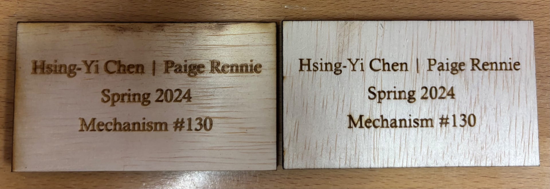
Laser cutting with and without tape
We spray painted all the pieces except the cams and the top of the base, completed the vinyl cutting and assembled it all together to get our final product!
Vinyl cutting
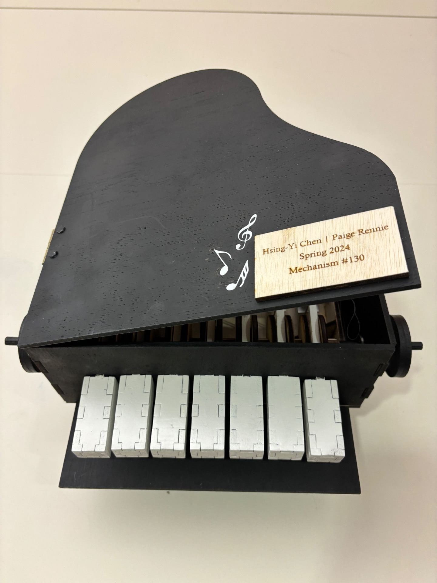
Our final project!
Another video playing all 7 notes with a full view of the inside of the piano
Link to powerpoint with a summary of our gates and processes
We made sure to clean up after ourselves throughout the whole process and the image below is one of the many clean tables we had after we worked on them.
Clean workspace
Cost of Production
Materials: 2’x2’x1/5″ Plywood x8 = $7.99 x 8 = $63.82 (Home Depot)
12″x12″x0.05″ Aluminum Metal Sheet x 0.5 = $15.76 x 0.5 = $7.88 (Online Metals)
Bearings x 2 = $1.99 x 2 = $3.98 (Autozone)
12″ x 40′ Vinyl Wrap x 0.07% = $14.30 x 0.07% = $1 (Amazon)
Wooden Balls x 7 = $14.99 x 0.014 = $0.21 (Amazon)
Metal Hinge x 1 = $1.50 (Menards)
Black Matt Spray Paint x 50% = $6.48 x 0.5 = $3.24 (Walmart)
White Gloss Spray Paint x 50% = $6.48 x 0.5 = $3.24 (Home Depot)
Labor: 80hrs x $15/hr = $1200
Laser Cutter Usage: 16hrs x $20/hr = $320
Water Jet Cutter: 1.5hrs x $20/hr = $30
Total Cost: $1634.87
OEDK Overheads: 15% of total cost = $1634.87 x 1.15 (covers using Lab Techs, random materials like foam, elastic bands, some sandpaper, drills, nuts and bolts, general wear and tear).
Total Cost of Production: $1880
