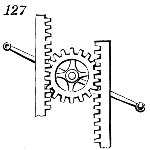
For our 3rd assignment, we were tasked with creating a 2D drawing of a machine taken from 507 Mechanical Movements using Adobe Illustrator. 507 Mechanical Movements is a neat site featuring drawings and animations of different mechanisms/motions. For my 2D drawing, I selected movement 127, a device made of a spur gear sandwiched between two racks. A lever is attached to the same shaft as the gear. Moving the lever up and down rotates the gear and causes the racks to move in an opposing linear motion. 127 is often used for air pumps.
To begin the drawing, I first downloaded an image of 127 from 507 Mechanical Movements and opened the image in Adobe Illustrator. I slightly decreased the opacity of the image, and then used the pen tool to trace over each part of the image.


I began by outlining the left rack. The straight left edge was fairly easy to draw, but tracing the teeth of the rack was rather tedious. I wanted to make all the teeth uniform and straight. To ensure all the teeth were in-line, I drew a green guideline marking the bottom cavity of the teeth down the length of the rack. From there, I traced one rack tooth. I copied the tooth and connected the tooth to the first segment using the join feature. I copied and pasted successively longer segments of teeth until the rack was completed. To draw the right-hand rack, I copied the left-hand rack and reflected the drawing over the y-axis.
Next, I traced the spur gear and the lever. I first drew the inner circle, two small internal circles, and the circles on the lever heads. Using the curvature tool, I traced over each of the four inner gear arches. I adjusted the arches to make sure that their paths intercepted the path of the outer circle. I drew the body of the lever using four line segments, connecting the lever heads to the internal circle of the gear.


Finally, I traced the gear teeth. I first traced the outer circle that the gear teeth border. Drawing the teeth gave me the most trouble out of all the other device components. Unfortunately, the gear teeth in the image of 127 do not appear uniform when the image is zoomed in. I experimented with several methods of drawing uniform gear teeth, including constructing a custom gear tooth using the rectangle or pen tool, that would appear to match the image. Ultimately, I decided to trace over one tooth, and copy/paste that teeth all around the edge of the outer circle. Rotating and joining each of the teeth to the outer circle was not exactly my definition of fun.


After all that work though, my drawing was complete!! Actually, that was not the case. After inspecting the whole drawing, I realized that the gear teeth were slightly too small, and did not all fit neatly with the rack. With a heavy heart, I increased the size of the gear teeth one by one.

For the last step, I removed the outer circle that the teeth border, and connected the bottoms of the gear using the pen tool.


Behold, my completed drawing!

Final Drawing
