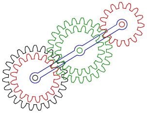
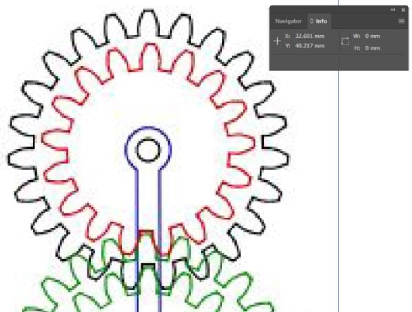
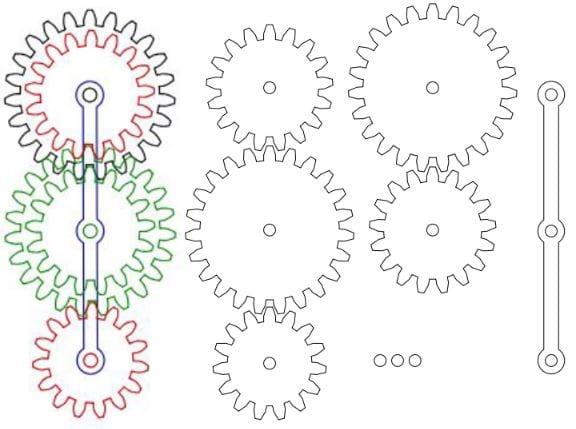
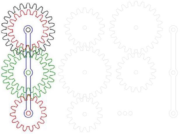
Tasked with making a 2D drawing of a mechanism from 507 mechanical movements, I decided to model an epicyclic train, mechanism 502 (pictured below, http://507movements.com/mm_502.html). This mechanism consists of 5 gears with two pairs placed concentrically. As the first step in making the 2D drawing, I opened a screenshot of the mechanism and played around with the image trace options. After trying a few image trace options, I decided against it because none of the types of image trace options allowed for a clean image. Some led to a sharp image where curved corners were lost or others led to a simplified image where entire gears were lost altogether. Instead, I decided to use the “Info” tool on Illustrator (pictured below). This tools shows live cursor position, so I used it to find dimensions for the gears. For most gears, I needed the inner diameter and the teeth size (which is the same for all gears).
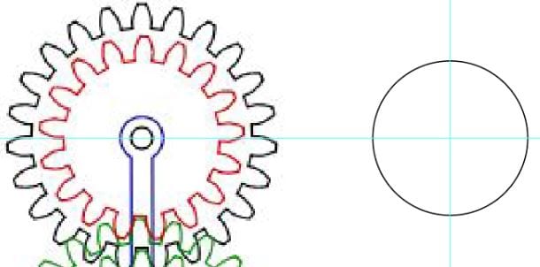
Next, I started drawing the first gear by creating a circle equal to its inner diameter using the “Ellipse” tool (pictured below). In the process, I learned about guidelines and used them to line up the circle in line horizontally with the first set of gears. Next, the gear teeth profile was drawn using simple lines and connected. The gear teeth lines should be grouped in order to form one shape.
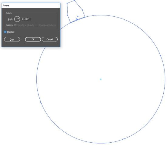
Once the gear teeth is done, it can be replicated to be rotated around the circle. In order to do this, select the teeth profile and use the “Rotate” tool, clicking on the circle’s center with “Alt” pressed down to bring up the box shown (pictured below). The degrees of rotation were determined by dividing 360 degrees by the number of teeth. After entering the number of degrees, check the “Copy” box in order to create a second gear tooth. In order to create all the rest of the gear teeth, press “Ctrl” + “d” repeatedly until finishing it around the circle. Note: When I was rotating my gear teeth, I also had the circle selected which led to multiple copies of the circle; this really messed me up in later steps so be careful to avoid this and only have the gear teeth selected.
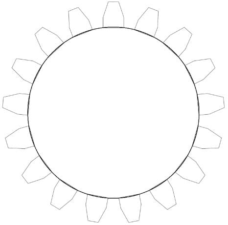
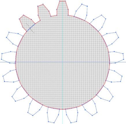
Once all shapes have been finalized (circle and gear teeth), the “Shape Builder Tool” can be used to combine them into one shape. After selecting all the shapes, the tool can be selected and all the gear teeth can be merged with the circle with a simple line dragged through them (pictured below). Once all the gear teeth are merged, the gear is complete, and all other gears can be created in the same fashion.
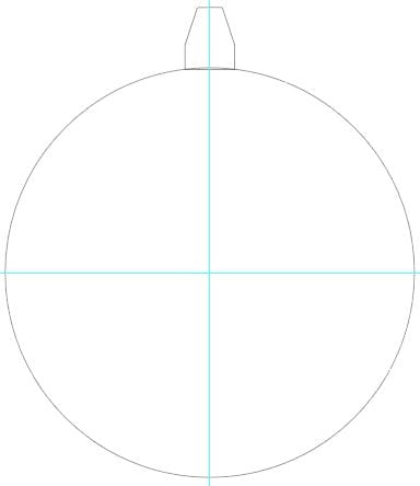
Next, the only thing left to model is the beam which travels across the gears and houses the dowels along which the gears are mounted. Again, guide lines were employed to mark the three rotational points, and the “Rectangle” tool was used to start the shape (pictured below). Next, three circles are drawn along the three guide lines intersecting with the horizontal center of the rectangle. To finalize the beam, the “Shape Builder Tool” is used to connect the rectangle and circles into one shape (steps pictured below).
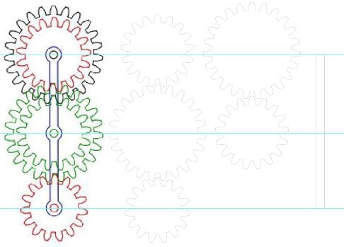
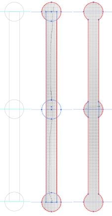
Lastly, some circles were added to the centers of each gear to mark the holes for dowels. As an optional component, circles at the bottom are added which could be laser cut out of a thicker piece (at least three times as thick as the other wood) and used as dowels. However, as a cleaner solution, dowel pins should be used to connect the gears and the beam. The final product is shown below.
The Adobe Illustrator file for this assignment can be downloaded from the link below.
The only cost consideration for this assignment was the time spent on modeling the mechanism. I spent a total of 3 hours, which can be totaled to $30 at $10/hour.
