For this assignment we had to depict a movement chosen from 507 Mechanical Movements, an antique engineering book, as a 2D drawing in Adobe Illustrator. I chose no. 92, “Ordinary crank motion,” because it seems like a widely applicable movement. I have some familiarity with Illustrator from all the laser cutting files we made in SEED for our shoulder model. Listening to Dr. Wettergreen give his workshop, though, I knew I still have much to learn.
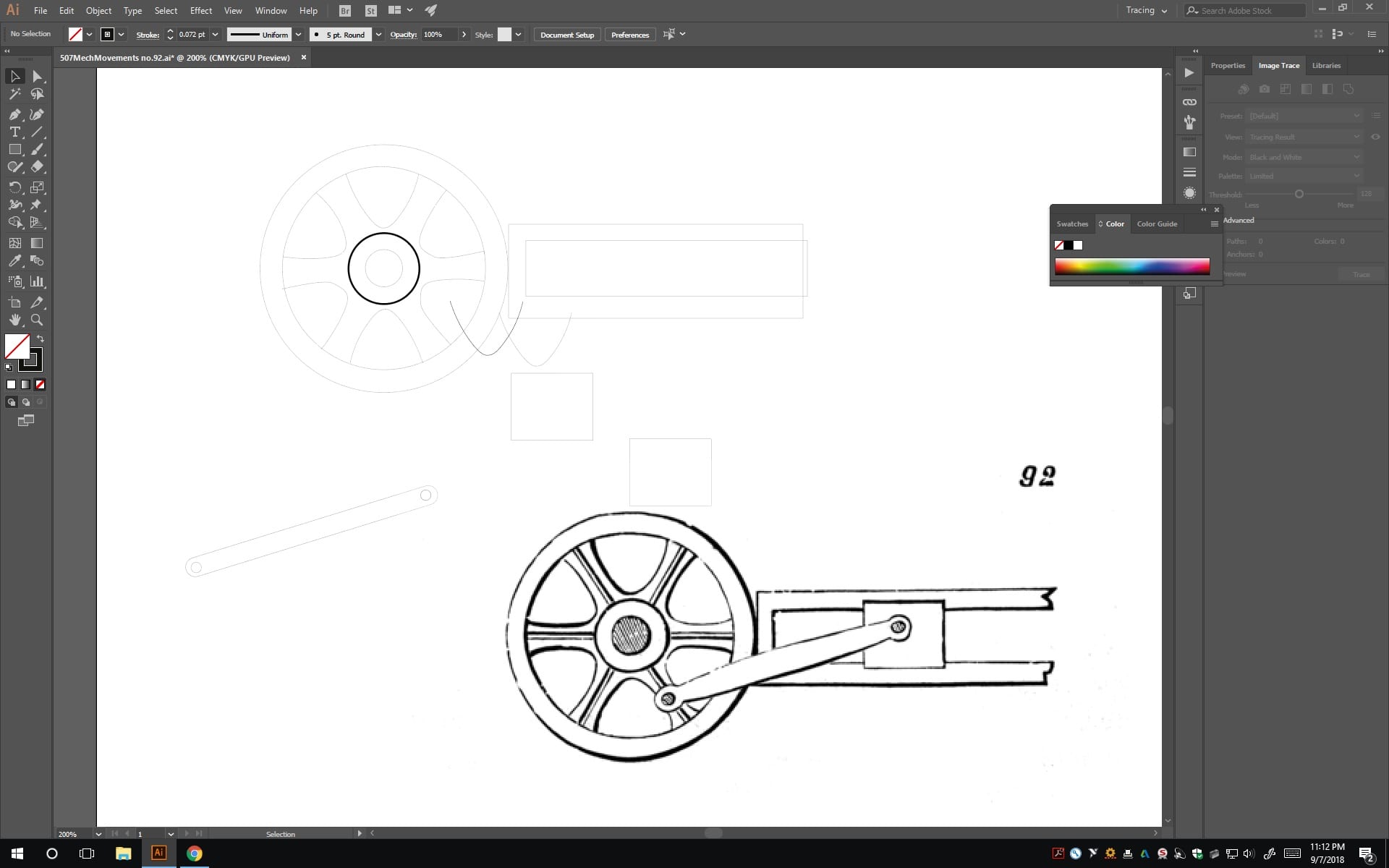
The assignment seemed easy enough- use image trace or rebuild to draw a simple mechanism. Image trace is only copy image, paste and a couple of clicks. That produced quite an unsatisfactory trace; no matter what filter I used the lines had gaps and wouldn’t ever work to laser cut. I decided to start from scratch and lay shapes over the image by hand to copy it.
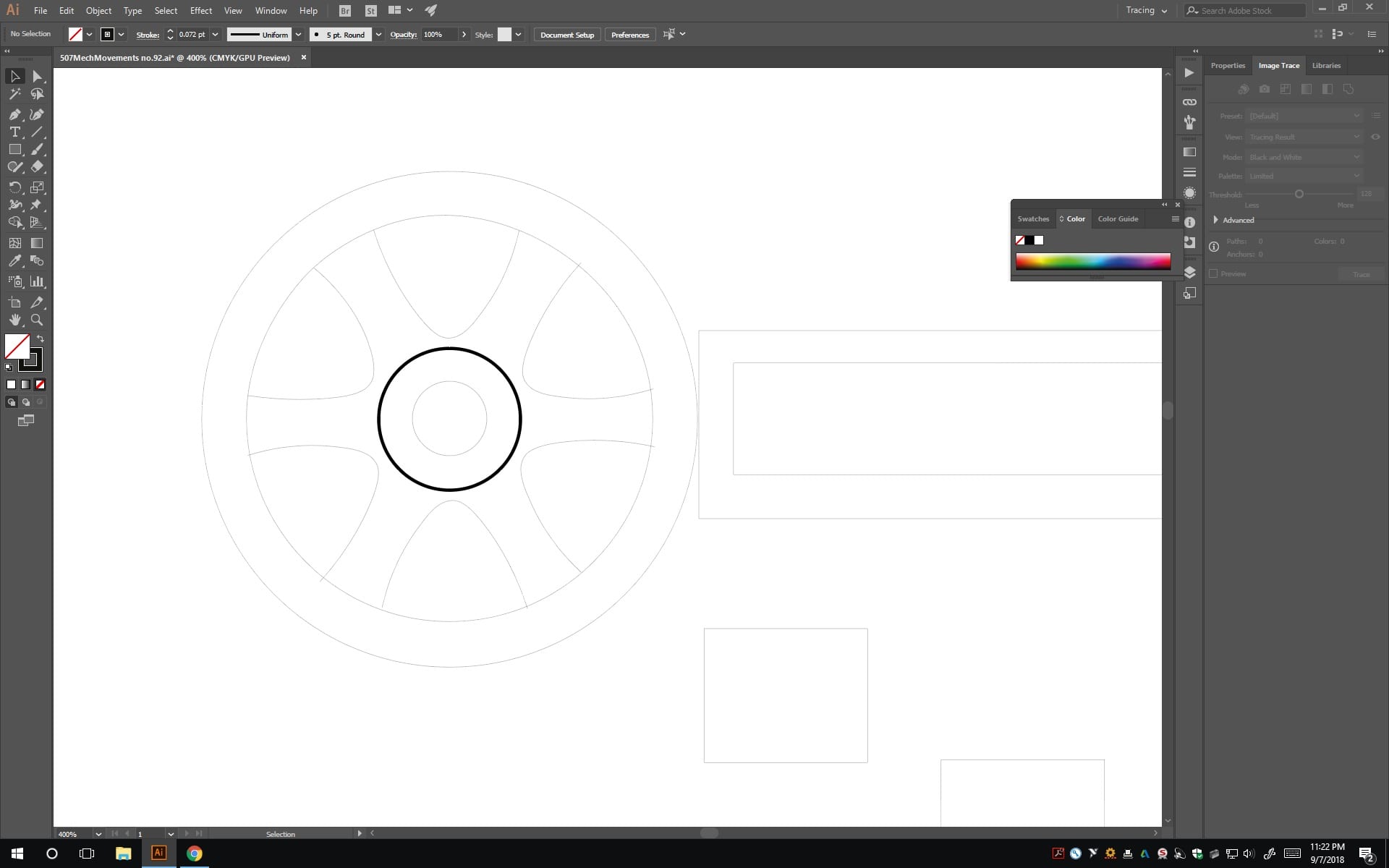
I set to work making rectangles, circles, and an oblong rod to connect the wheel to the sliding block. For the wheel I wanted to try replicating the curved cutouts, so I used the curvature tool and freehanded one over the image. I got an approximation and moved it over to my wheel, making six copies of it and rotating them at 60 degree intervals to go around the wheel. I was halfway in when the asymmetry started bothering me. I adjusted the curve and this time checked it against its reflection. Close enough for me, for an aesthetic element. The ones in the drawing are neither identical nor symmetric, and I made mine a bit more regular by copying the same curve to all six directions.
Ta-da! I had a wheel. Well, not a useful one. Since I put the stroke at 0.001 inches, this would produce a lovely star shape and a ring, with only the dark axel decorative circle rastered. I was just about to try using the cutting tool and joining each segment individually when Nick (Escobar) kindly reminded me of shape builder.
You see, after an, *ahem* trying initial experience with Shape Builder this summer, I’d been convinced it was only a way to waste 45 minutes of your life turning a nicely aligned set of shapes into an incomprehensible mess. So no, not my go to.
Luckily, Dr. Wettergreen is better at showing the mechanics of the tool than the animated video tutorial Grant and I had been trying to follow. He explained how to select multiple overlapping shapes and then click Shape Builder and drag through to connect them. I tried this on my wheel, changing tactics to make the curves into closed shapes and merge them with the outer ring. It worked like a charm! This technique also worked great for making that U-shaped track for the sliding bar.
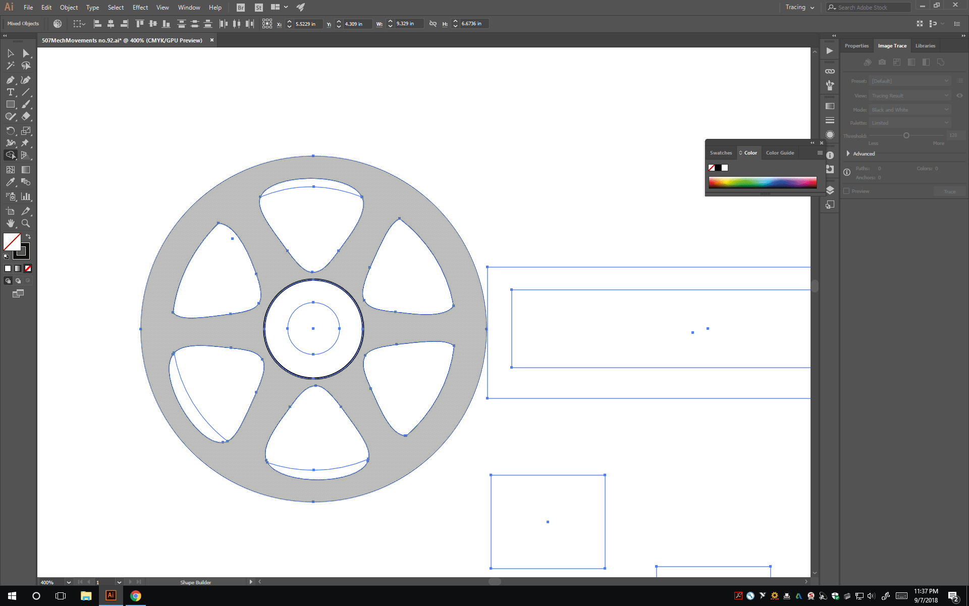
In the process of filling in the overlap between the curve-triangle and the rim.
A comment: the entire time I was working, every new shape I drew would start with no fill, no stroke. When I turned stroke to black, it would be at 1 pt and I had to reset to 0.001 in (0.072 pt) each time. I don’t know exactly how to change that default, but it certainly would be more convenient to have it set to the cutting width and a line I can see. I believe the output files of MakeABox have a preset that gives the correct line width, so drawing shapes on those files I hadn’t run into this problem before.
As I moved toward finishing what was directly shown in the drawing, adding pins in the wheel and bar, I attempted to make it functional as well as representational. I added a middle and back layer to the sliding bar to let it be confined along a track, and made small donut shapes that could hold the rod on a dowel and let it and the wheel rotate freely. I also made a backplate with “92” that could mount the device. Here it is, all assembled in Illustrator!
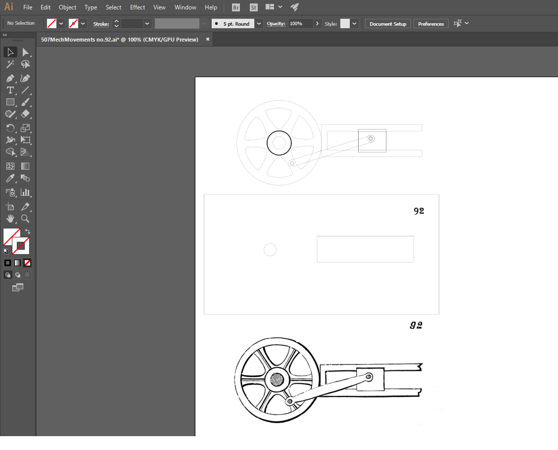
My final file has all the pieces laid out as if to laser cut. I thought about the layers it would have and deleted the U piece because I’m pretty sure it would be one layer behind the wheel, making a hole in the backplate a more effective channel. Attached is the file for Mechanical Movement no. 92. I know what I’ll try printing in the laser cutter this week!
507MechMovements no.92 final-1vnuyb8
