In the next assignment for ENGI 210, the task was to recreate one of the 507 Mechanical Movements. I decided to recreate the 205th Mechanical Movement. The animation can be found here. The mechanical movement is “a wheel driven by a pinion of two teeth. The pinion consists in reality of two cams, which gear with two distinct series of teeth on opposite sides of the wheel, the teeth of one series alternating in position with those of the other.”
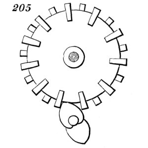
The task was to use Adobe Illustrator to recreate the drawing with to-scale dimensions. Initially I started by importing a picture of the mechanism. Then I used the “Image Trace” tool to trace the image and convert it into vectors. A problem that arose was that the image was old, so the trace did not work in all parts of the drawing. I decided to instead manually trace all of the components of the picture. I began with drawing the large circle and then began creating the teeth that surround the circle. I first drew one tooth and combined it using the shape builder tool. The tooth was then copied around the circle using the rotate tool. Since there was an odd number of teeth, they had to be rotated 32.72 degrees repeatedly all around the circle.

Initial Drawing
Next I decided to draw the spade looking gear by combining two arc figures and a circle. This was made into one shape using the shape builder tool. Two of these spades are needed for the final design, so I copied and pasted. Seen in the image below are also two rings. These are spacers that go between the two spades. At this point all of the parts in the drawing are done, but an end purpose is to be able to laser cut the design, so there were additional steps that I took to accomplish this.

Spade Drawing
For the laser cutting I planned the design to be cut on a 1/8″ thick piece of plywood. Since the machine requires two sides, each with independent teeth, two half needed to be made. One large circle in the current orientation and one rotated 16.36 degrees. Since the teeth had to be cut separate and glued on, I decided that the best way to accomplish this was to etch a space in the large circles that would show where the teeth need to go. This would help ensure that there is the same space between all the teeth on each side. Additionally I decided that the large circle would spin on a 3/4″ dowel rod and the spade gears would rotate around a 1/4″ down rod.

Laser Cutter Settings
The image below shows the basic parts needed to complete the assembly. The shapes were all modified with a .001 inch line so that they could be cut on the laser cutter. The red is where the laser cutter will etch and not cut. Additionally, since both large circles have to be at a 16.36 degree offset from each other, to make it easy, I decided to incorporate a tab that would be cut out in the middle of both of the large circles. This cutout can then be filled using each of the two small rectangles that act as the keys. The point of this is so that both of the circles line up correctly with the correct offset. Also, the two small rings that were initially for spade gear spacing were made bigger. The reason for this is so that the spacer would ride along the outer edge of the large circle.

Basic Assembly
I knew that the design was not finished. If indeed this was going to be laser cut, then in order for the machine to work properly, there would have to be a stand to be able to mount it on. The Extra Assembly serves this purpose. There additional parts I designed are to allow a stand to be built to easily display the machine. In the image there are many parts. There is a handle that would be attached to the 1/4″ dowel that would be spinning the spade gears. Located besides the handle on the top row are four feet spaces that would need to be glued to the bottom plate (located at the bottom) so that the rings would not hit the surface. What are the rings? Well that is the next part I will explain. The way I envisioned it, there would be two dowels, cut to indeterminate length. The dowels would be built into the bottom plate as follows. First a small ring would be glued to the end of the dowel, then the dowel would be inserted into the bottom plate from the back. Next, there would be another small ring glued to the dowel that would keep it from moving up or down in the hole (the rings are not glued to the bottom plate, be careful when gluing). Next there would be another small ring glued somewhere along the dowel. After the glue dries, one spade gear would go followed be the two large spacers and finally the other spade gear. The spade gears would be glued to the spacers and the spacers to each other, they would also be glued to the small ring that was inserted before. Lastly another small ring would be glued to the dowel, pressed against the spade gear, followed by the handle. The small circle can be glued on to the end of the dowel for aesthetic purposes. This process will be repeated with the large dowel and the large circles, the only difference being that there is no handle to attach at the end, so there is no fourth large ring. Instead there is just an end cap that would be glued to the end of the dowel. Make sure the two sets matchup with each other and interact the way they should. The dowels can be cut down to decrease the length they protrude out.

Extra Assembly
The last few laser cutting parts were made a little beyond what the assignment requested, but I thought it would be neat to think about how to actually get this moving in the real world and what structure it would require. None of this has been tested in actuality, so it still needs to be cut and tested to see if my design will actually work as intended.
Attached are the two Illustrator files needed to make this. Open them, change them, make them 100 times better. That is what tinkering is all about. Go make something amazing!
