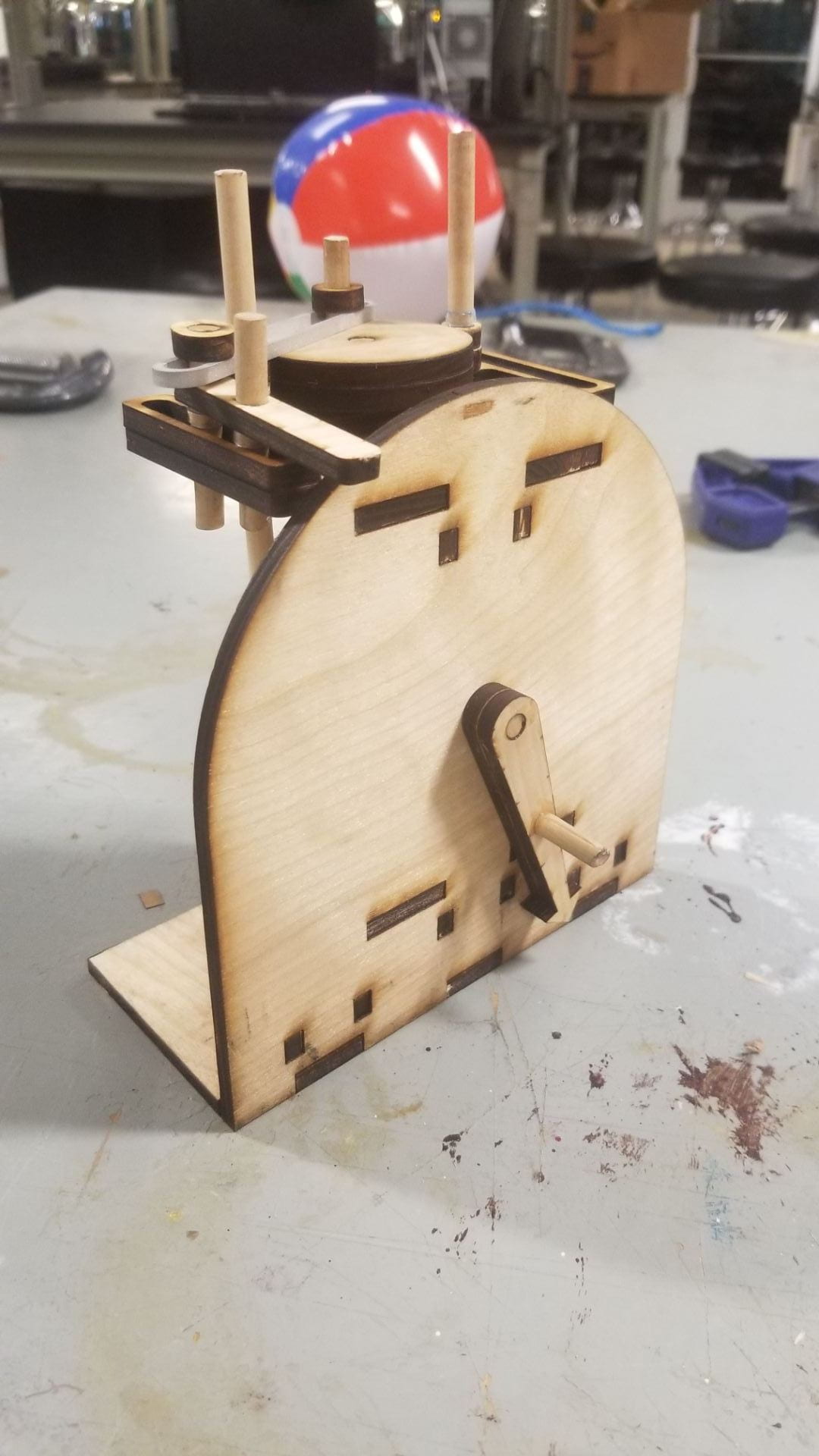
I started this project with a goal of incorporating some motion that does not easily translate into 2 dimensional laser cut parts, and decided I wanted to style the machine after a cuckoo clock. In my initial planning, I decided the motion would begin with a hand crank on the face of the “clock,” travel through some sort of right angle gearing that I hoped would be a challenge to achieve on the laser cutter, then finally translate to linear motion as the bird moves out in front of the clock face. For the right angle gear connection, I briefly considered trying to make a layered bevel gear that would be glued together then sanded down, however, I found mechanical motion 26 and decided to make a crown-wheel to cage gear right angle connection by laser cutting discs with insert holes for 1/8th inch dowels. This turned out to be quite easy, and ran extremely smoothly when testing them after I did a bit of sanding work to smooth out the fit. This rotation is then applied to a combination of mechanical motion 101 and 131 to create linear motion. I decided to utilize the rotating disc of 131 in a second application of 101 that ran parallel to the first, but from the opposite side of the disc. This creates a sequence when one bar will extend slowly then retract rapidly while the other extends rapidly before retracting slowly with a slight off set from the first. With this design in mind, I set out prototyping.
I started out with a solidworks model to design and check dimensions while still designing for laser cut parts from a known thickness of material. When I was satisfied with the assembly, I exported the individual parts as DXF files and laser cut them on cardboard.
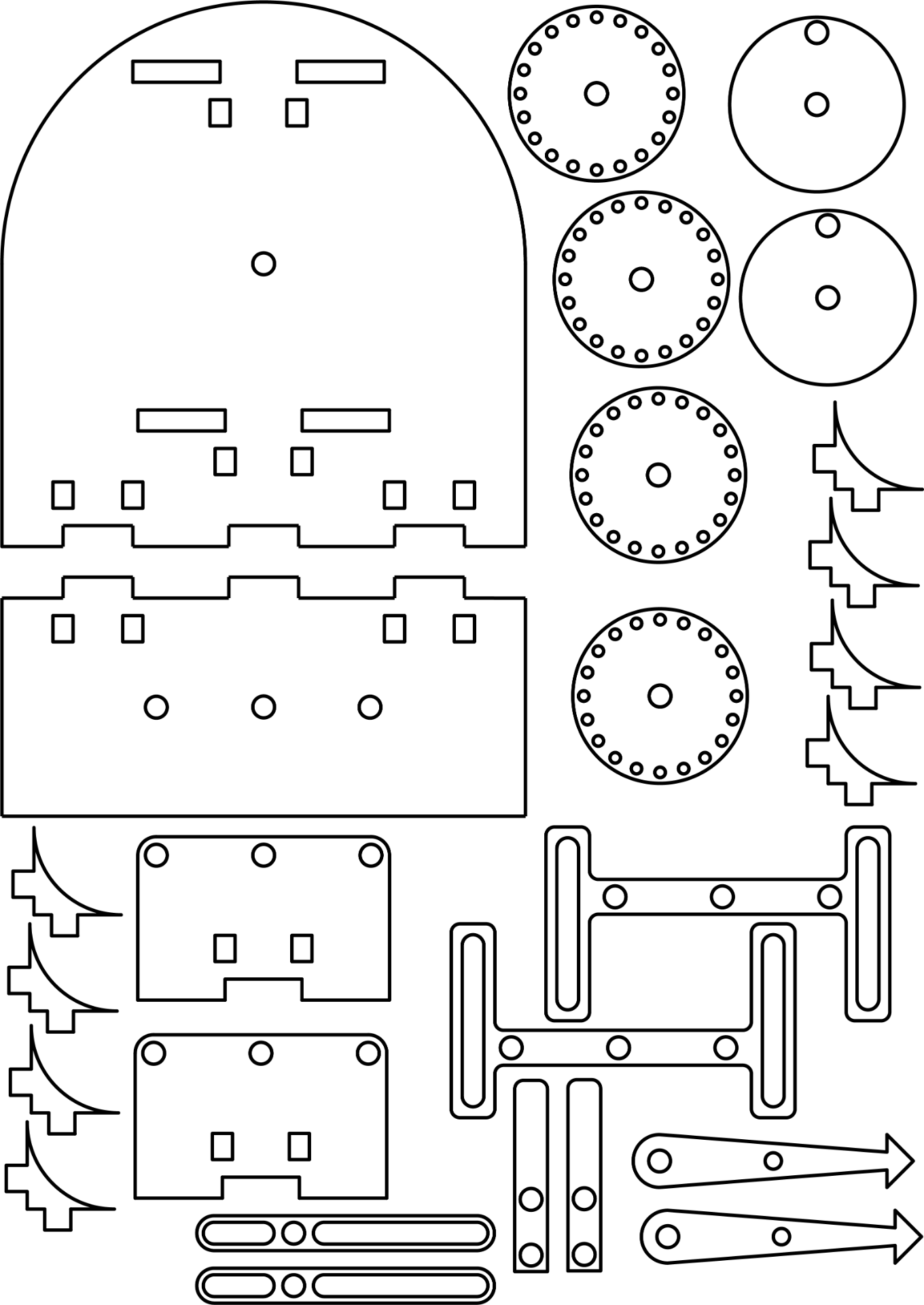
I assembled two cardboard prototypes in this way, then moved on to wood. After I began assembling the wooden prototype, I noticed that the tolerances used with cardboard did not work with the new material, so I went back and adjusted all the part files in Adobe Illustrator to create a tighter fit. With a bit of trial and error, I got all of the parts to work together with a friction fit, aside from the right angle gear system, and hand crank, as I had already glued them together on the previous wooden prototype and did not have the time to spend on rebuilding it. I also laser cut the incorrect file for the base, and the laser cutter was not working for the rest of the time I had to work, so some of the holes there either do not line up, or were too small and broke the corner braces during assembly. From the same problem, I never was able to laser cut the parts for the second linear motion system, and therefore could not assemble it. Testing the wooden prototype I had, the linear motion conversion was sticking due to friction between the rotating disc and the bar that it drives, so I opted to water-jet an aluminum bar to replace the wooden one that was binding. I took the aluminum bar, tested it to find the whole mechanism moved with no resistances, and finished the part with sand blasting. After reinstalling the part, I was forced to leave the OEDK.
To finish the machine, I would have re-cut the base to get the holes aligned properly, stained all the wood components, added a decorative plasma cut and polished bird or two, applied a layer of polyurethane to all parts, then reassembled the device.
Cost Estimate-
The final product would use a 1/8” wooden dowel, a 1/4” wooden dowel, a 1/4” inch thick sheet of plywood, 1/4” inch aluminum sheeting, wood glue, and wipe on Tung oil and polyurethane. Sourcing prices from Home Depot;
-1/8” Dowel: $0.55
-1/4” Dowel: $.86
-1/4” Plywood: $13.96
-1/4” Aluminum Sheet: $29.98
-Tung Oil: $20.48
-Wipe on Polyurethane: $12.98
-Labor: 30 hours at $10/hr: $300
This creates a total material cost of $378.81, though there would be a significant amount of excess aluminum, tung oil, and wipe on polyurethane that would be sufficient for many more copies to be made.
