For my midterm project I decided to build a battering ram! woohoo! My design was inspired by a number of mechanical motions from the 507 Mechanical Movements website. For the ram mechanism I decided to go with a double rack and pinion as seen in mechanical movement 118 below. The benefit of this design is that it doubles the length that the ram would travel for every piston stroke. This mechanism was important because it let me keep the rack and pinion mechanism inside the battering ram and keep it relatively small compared to the distance it would travel.

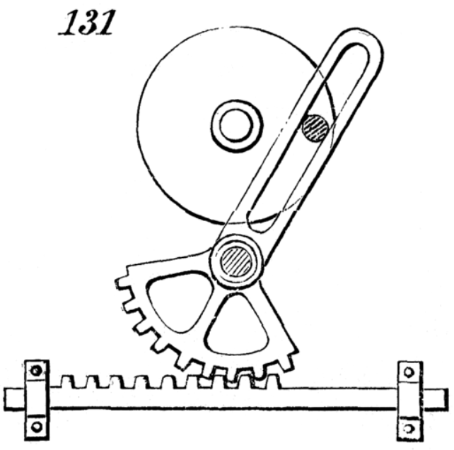
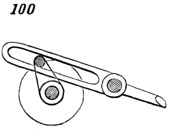
The next component I decided to include was a variation on mechanical movements 100 and 131. These two mechanisms create a rotational motion with varying speed. This is what would give the battering ram the illusion of being pulled back slowly and rammed forward quickly!
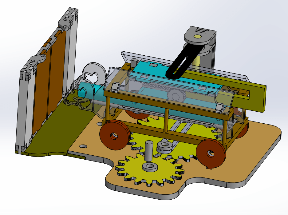
The first step of my process was to design everything in solidworks. I was taking on a pretty large project and I wanted to make sure that everything would work and fit together on the computer before I started physically making my device. Below is one of my early CAD models.

My low fidelity prototype for this project was a combination of the above cad model and I also laser cut a replica of mechanical movement 100 out of cardboard just so I could get a feel for how it would work. I would constantly be updating and making changes to my CAD file. The second version of the ram is below. As I added a base and began to make changes to the rack and pinion gear setup.

Before I started to cut out my components out of wood and acrylic, I needed to see if my rack and pinion components could work To design the rack and pinion, I downloaded CAD models of the gear and rack from McMaster Carr and modified them in Solidworks. This process took me way longer then it should have as I wasn’t super familiar with all of the properties associated with gears and how to match them up to the correct rack. Eventually I found a gear and rack that matched up with each other and started the water jetting process. I also ran into issues when cutting them out, the kerf on the water jet was cutting into the teeth way too much and made the teeth into little spikes that couldn’t grip on to each other. Eventually I was able to make changes on the cutting software to offset the path of the water jet so that the teeth would be the right size.
After that struggle I started to cut out all of my different components. To make the actual ram piece, I took a dowel of diameter 1.25″ and cut a flat side into it using the electric planar in the woodshop. I shaved it down until it was 1″ tall. I spray painted most of my components and added different gradients to them, overall just letting myself be creative with the post processing. I didn’t want to constrain myself to any sort of color scheme and I didn’t want to make my project scary looking!

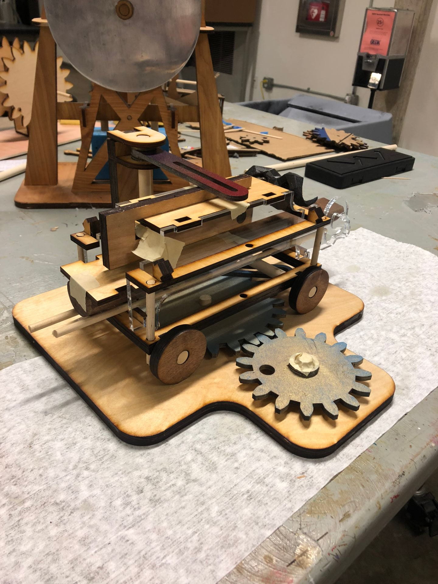
Right around the time when our classes got cancelled due to the virus, I started to toy around with the idea of adding a door to the front of the battering ram for it to push into. But first, I wanted to make sure everything fit together so I made a mock assembly of my project without any glue and just tape.

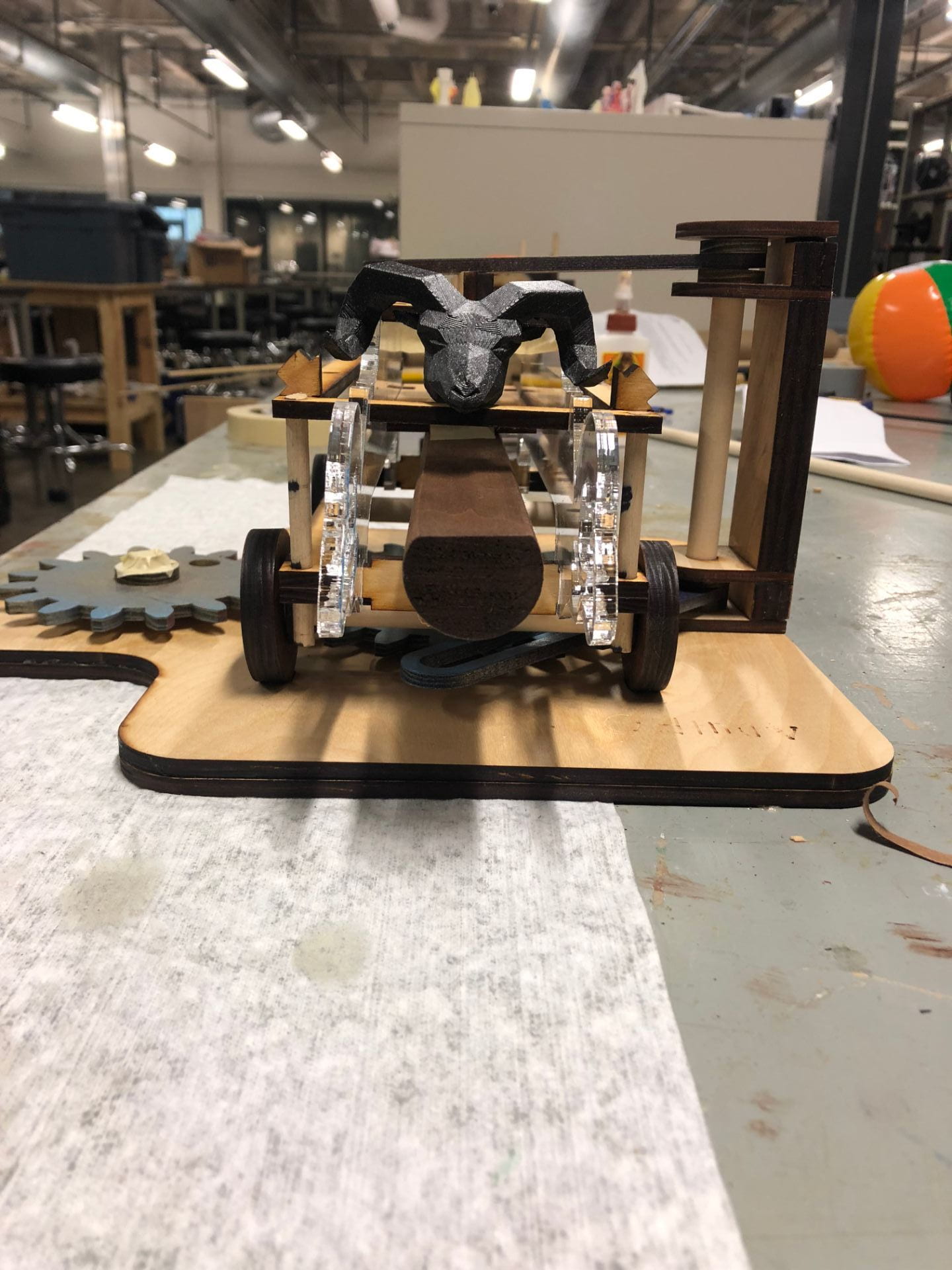
Front view, (3D printed ram head just for fun!)

My final CAD model with the door component can be seen below!

And here are two videos of the battering ram in action! The first video is of the entire machine while the second video just shows the door and ram components!
Even though I didn’t get to finish my project, all the work I have done up to this point took me atleast 30-40 hours. The CAD alone took me 20-25 hours to do. In addition to that I spent atleast 5-10 hours in the OEDK cutting and post processing my parts.
