Name: Avinash Shivakumar
For this assignment, we were tasked with designing our midterm projects using 3D modelling software. Last semester, I took MECH 403 (Computer-Aided Design) with Dr. Ed Akin. MECH 403 focused on teaching us how to comfortably use SolidWorks for 3D modelling, analysis, and simulation purposes. So, I am now quite comfortable with and confident in my abilities to use SolidWorks as a 3D modelling tool. I attempted to learn to use IronCAD in class when Dr. Wettergreen was teaching us, but I found many of the features rather counterintuitive as compared to in SolidWorks. For example, one feature in SolidWorks that I feel truly facilitates its use is the ease of sketching and extruding solid features and repositioning orientations for viewing. Many of these features are not so simple to execute in IronCAD, at least not with my level of expertise in and familiarity with it. So, I used SolidWorks to complete this assignment, with Dr. Wettergreen’s permission.
For my midterm project, I designed and constructed a harmonic oscillation punch machine (and I gave it a slightly rustic, worn look, which I could not easily duplicate in the same way in SolidWorks). The machine worked through manual rotation adjustment of the rounded triangular paddle, which would, in turn, translate and rotate the lever arm in order to raise or lower the large punch dowel. I reproduced this mechanism along with its motions (as described below) in SolidWorks in a 3D CAD format. One important thing to note about the CAD design, however, is that all dimensions are as accurate as possible, bordering on exact, or as close as can be. Because of this, the CAD recreation is not an accurate indicator of how the assembly might appear in real life as a physical model. Extra spacing might be necessitated in a physical model in order to allow for the movement of some parts to overcome contact frictional forces. If this were laser cut from the 2D drawings, as was the case here, then the resulting pieces would differ slightly, allowing a little more spacing, from the ideal drawings. If, on the other hand, the assembly were to be 3D printed, the holes might come out a little small compared to the CAD construction. This would potentially impede the entry of any pegs or dowels that might be required in the assembly, as would be required here.
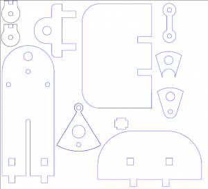
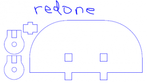
Most of the construction of parts that I had to do was facilitated by the fact that, when Adobe Illustrator proved none too helpful in the design stages of my midterm project, I turned to SolidWorks for my 2D drawing needs. In doing so, I managed to save all of my assembly components as 2D drawings in a SolidWorks compatible format. In my 2D modelling stage, I had determined that certain pieces in my drawing were not dimensioned in a manner that would allow them to fit properly and stably within the entire assembly when laser cut, so I re-did these parts in a separate SolidWorks drawing file. The drawings are reproduced below:
From here, all I needed to do was extrude the 2D parts in separate SolidWorks Part files to give them thickness and then import them into a single SolidWorks Assembly file, remembering to import some parts multiple times in order to account for the layering I used in my actual midterm assembly. Once in the Assembly file, I merely mated (using the SolidWorks Mates feature) all of the relevant edges and surfaces in order to fit all of the component parts together as I had done in my midterm assembly; I continued to mate parts and edges together until SolidWorks recognized the assembly as being fully defined. For a little added bonus, I mated certain edges so that the relevant parts would move as they did in the physical model (i.e. my 3D model can oscillate harmonically in a punch motion, albeit without the punch dowel). As per Dr. Wettergreen’s specifications, I did not include any dowels in my 3D model.
For my extrusions, I used a thickness of 0.2 in. because this is the approximate thickness measurement I obtained while designing and constructing my model for the midterm.
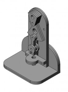
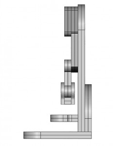
Below are an isometric, front, right, and back view of my 3D CAD model, respectively.
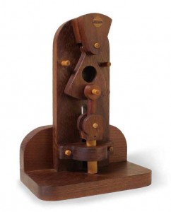
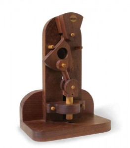
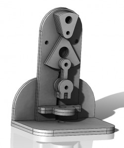
For comparison, pictures of the actual model, as seen in the book and as constructed for the midterm, respectively, are reproduced below, alongside a shaded version of my CAD reconstruction that aims to recreate the worn, rustic image I had in mind:
I also created a rendered video demonstration of how the punch machine mechanism works (still not including any of the dowels); it can be accessed here: Punch Machine Assembly.
