The good news is that I don’t think I can make a pun on 3D-Printing, so the puns will probably stop. (Off-owl. A-fowl. Afoul?)
This project is brought to you about a week late (with permission) due to a host of unforeseen complications. This week, we were expected to make CAD renderings of our midterm projects (found here) using the CAD package of our choice; I ended up using IronCAD, a 3D rendering software whose basics we covered in class. My initial plan was to import my 2D files that I used to laser cut from Adobe Illustrator into IronCAD, allowing me to extrude the files into three-dimensions. Because this entire project was laser-cut, all the pieces of my project barring dowels were prisms, meaning I could extrude them directly from my illustrator files to .183 inch thickness, the thickness of wood that I lasercut. Therefore, what would have been a very daunting task became very simple using a simple process of exporting my Adobe Illustrator files into .dwg formats, which could be imported into IronCAD and then extruded using IronCAD’s helpful extrude feature.
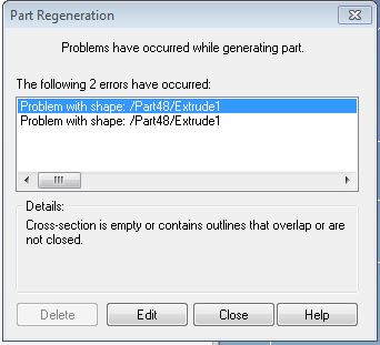
(this isn’t the exact error message that I received, nor is the part above anything from my actual project; however, for visualization purposes, I fabricated an example part that would generate the same error message in IronCAD)
As it turns out, Adobe Illustrator does not export entirely clean files–no matter how the .ai files read in Illustrator, they always appear in IronCAD as slightly disjointed. IronCAD then cannot extrude a shape that has no closed edges (or overlapping edges, or lone points, or edges that consist of two lines, all of which are problems from Illustrator’s imported files and all of which are included in the image above), meaning all extrusions will fail. This proved rather unfortunate to my ability to generate satisfactory CAD files, as the result from such an extrusion was either a failed extrusion (blank space) or a rectangular slab with approximate dimensions of the attempted extrusion. This is bad.
As it turns out, other software packages such as Autodesk and SolidWorks don’t have this problem, but I didn’t learn about that until I was well underway with my IronCADventure. I ended up CAD’ing the extruded pieces from scratch, using the techniques I’d learned in the IronCAD suite to assist me. I started first with the rectangular gears and slabs, as these were the simplest pieces to design and would allow me to get my feet wet regarding IronCAD’s operation/functions. For instance, I found that rudimentary gears can be created fairly quickly and easily in IronCAD using the circular pattern function, which will clone a line or group of lines in a radial pattern. I also found it easier to use the extrude wizard first, rather than making a 2D sketch and attempting to extrude from the sketch. By selecting the part I wanted to add to in the side tab and then using the extrude function, I was able to extrude parts that were still within my main part, allowing them to interact with one another.
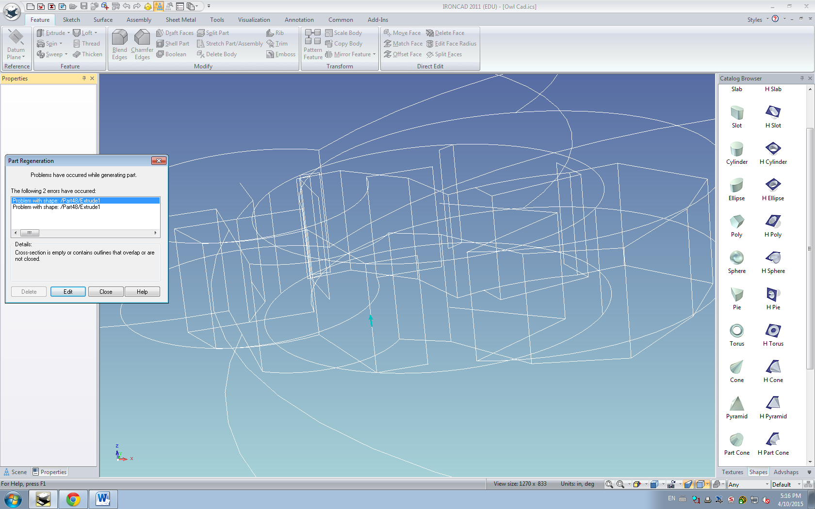
Forty-four radial repetitions shown above. Note that each radial repetition can create a basic tooth for this gear. Specifics such as the number of repetitions, the angle between repetitions (defaults to the number which allows for coverage of a complete circle), and the radius of radial repetition can be adjusted using options to the right. I actually wanted fewer repetitions than the number in the image above, so I scaled down to twenty-four repetitions.
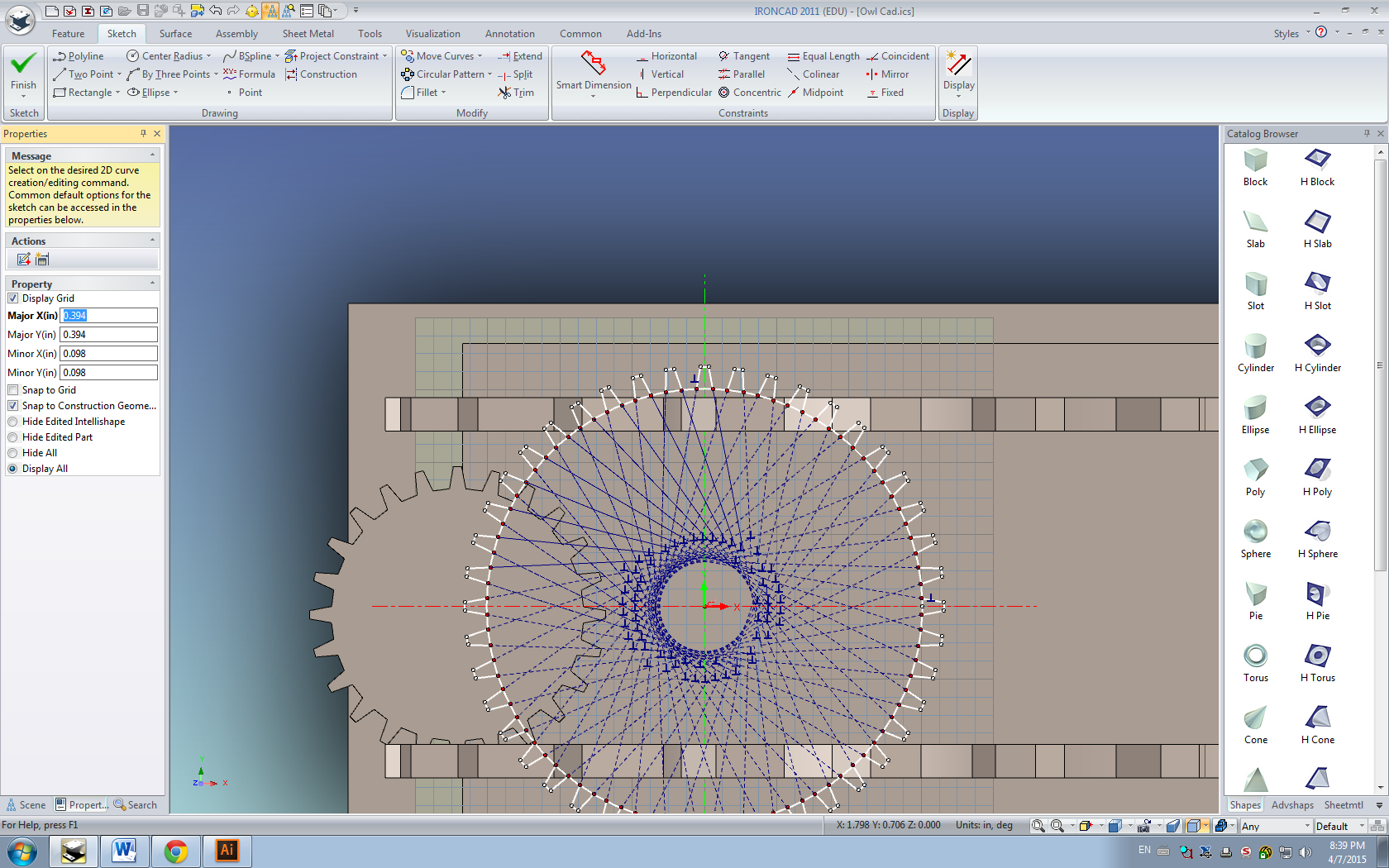
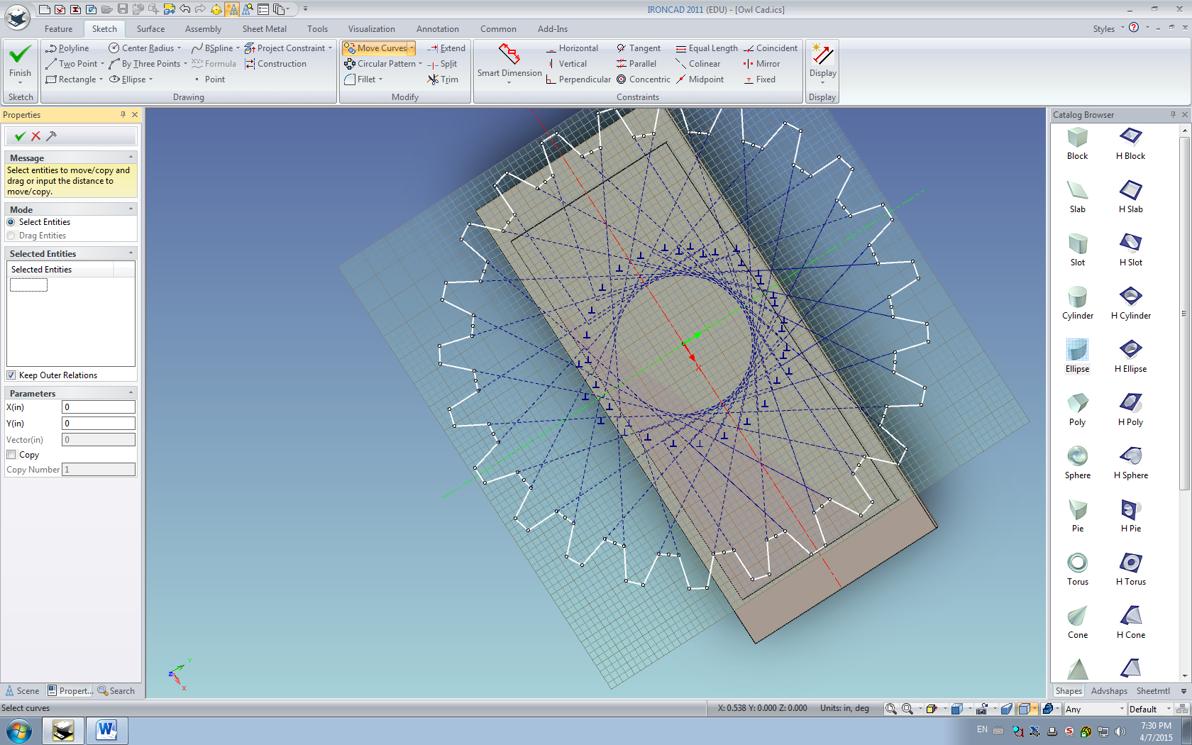
I was actually able to see an example of one of my previous errors in action. The dotted blue lines outside of the shape indicate that IronCAD perceives some part of the shape to be extruded as being outside of the boundary of the shape I wanted to extrude–what this effectively means is that, should I attempt to extrude this shape, I’ll get an error message identical to the ones that I got with the Adobe Illustrator files. This is bad.
As we found out, bad things in CAD lead to the error message.
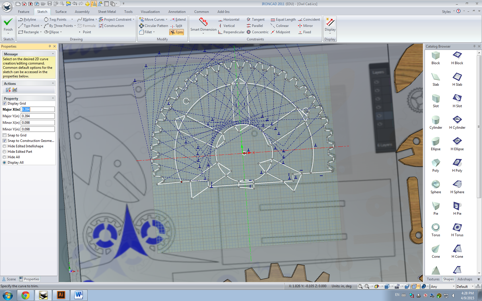
To clean up this image, I needed to delete the extra lines and also remove any hanging points. I found that the trim function does this best, as I can click on line segments that I wish to remove. The trim function will only remove line segments in small pieces: it will only remove up to intersections of other line segments, allowing for the rapid removal of small lines such as the ones between each gear tooth. IronCAD’s error points appear as red dots–I found that if there are red dots in my 2D sketch, IronCAD will get angry and refuse to CAD them. This is bad.
I actually cannot convey how many times I saw this error message. Pasting it in this blog four times seems to help.
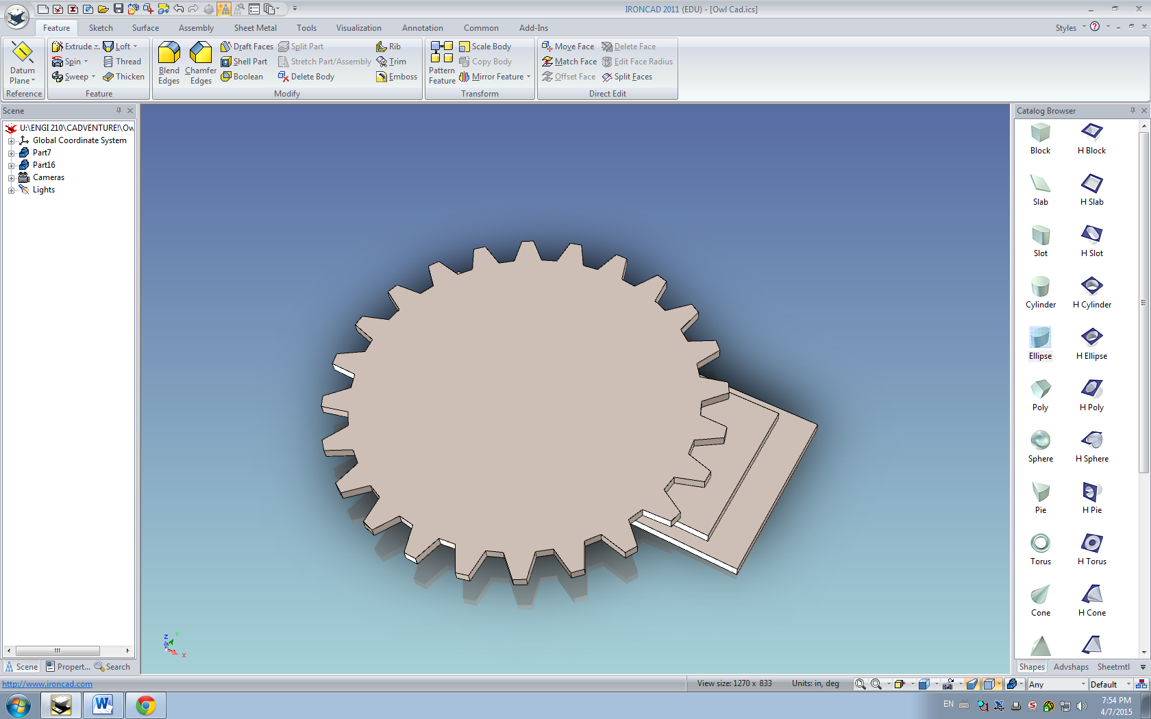
However, if the 2D sketch plane only has white points, the extrusion will work (usually). After some finagling, I was able to extrude a gear successfully, only to find out that I had created a gear with the same amount of teeth as my smallest gear while having the radius of my largest gear. However, I was able to redo them much faster the second time.
Now that I had an accurate understanding of how to extrude custom-made objects, I decided that I was able to extrude the rest of my pieces in a similar manner. I began with the CAD for the base, largely because I wanted to refine my talents practicing there before moving on to the larger challenge of re-designing the wings, tail, and face. For the base gears, which had some degree of internal geometry to consider, I first created a complete circular gear (the final base gear is approximately 2/3 of an actual gear, with the rest being attached to the rectangular portion of the base). I then used the polyline drawing tool in the extrusion wizard to add on the six thickened segments that served as internal support. The circle wizard feature, which allowed me to customize the center point and radius of the circles I created, was very useful in maintaining internal symmetry.
(slight spoilers for what I tried next)
Note that this markup is full of red dots and extra lines. This is bad.
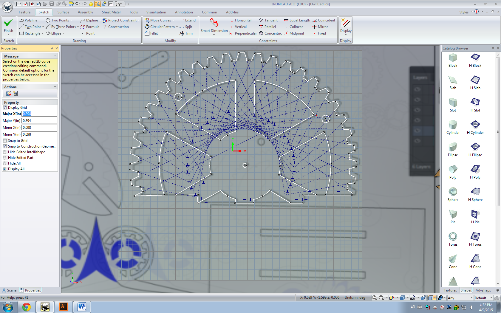
However, using the trim feature, I was able to remove unnecessary lines once more.

Note that, even though this piece appears to be extrudable, it isn’t, as there are still red dots. These red dots indicate, upon zooming in very closely, that the two line segments are actually not connected. IronCAD cannot extrude an open-bounded curve, and as such it will, again, fail to extrude the shape. This is bad.
Luckily, by this point, I had gotten into the habit of selecting all of my points and copying them (this function behaves similarly to copy/paste in any computer, but with 2D sketch points) before extruding, meaning I wouldn’t have to re-sketch them if the extrusion failed.
I ended up deleting all of the questionable line segments that were causing extrusion issues and redrawing them with the polyline tool, creating a shape that has only white dots that could be extruded.
Actually, if you didn’t look carefully (I didn’t), there’s a single red dot in the upper right that indicates that I forgot to delete an extra line segment. This is, of course, bad.
After much more finagling, I finally managed to extrude a successful base gear of appropriate dimensions. Using the triball’s copy feature, I was able to make a second copy of the base gear 1.098 inches away from the first (this number is .183*6, as there are six layers of gap between each of the bases). I also took this time to make four copies of the large and small gears that I had designed earlier and fit them into the base in their respective locations.
I was then faced with the difficult task of finding out how to re-design the wings, face, and tail of the owl. While it had been fairly simple to design the gears and base, as they consisted of radially symmetric shapes, the rest of the owl was far more abstract. However, my answer came in the form of something unexpected, when I was applying different wood textures to my pieces to see which one looked the nicest.
I realized that I could take a snapshot of my .ai pieces and apply them as a smart-paint background to a large, rectangular slab–this would essentially import them into IronCAD, although a few extra steps would be necessary. In illustrator, I took a screenshot of my workspace that contained the pieces I still had to CAD (barring duplicates, as it would be much easier to clone them in IronCAD rather than re-draw them twice) and then edited it to have a 3:2 aspect ratio. Any aspect ratio would’ve sufficed, but 3:2 fit nicely with the dimensions of my Illustrator artboard and was easy to remember. I then created a slab in IronCAD that was 30×20 inches and applied the screenshot as a smart-paint texture to the slab. This prevented any distortion of dimensions in the projection. There were some minor difficulties in getting the size to match up; however, if I scaled down the size of the slab, the size of the projection scaled down appropriately. In this fashion, I was able to get exact copies of my .ai files into IronCAD, where I could trace them using the extrude wizard.
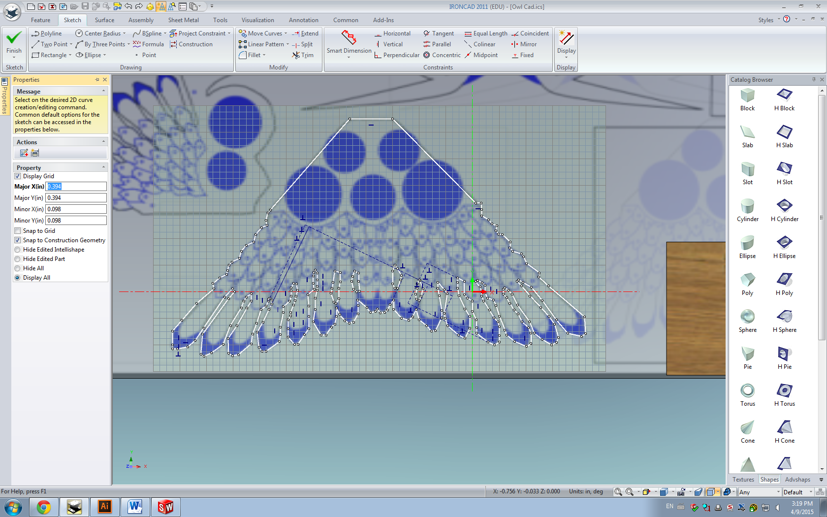
Because the projection is identical in dimension to my desired final product (I found that resizing the slab to have the initial dimensions correct was far easier than having wrong initial dimensions and resizing the final product), I only needed to trace over the outline in the extrude wizard and then extrude the piece.
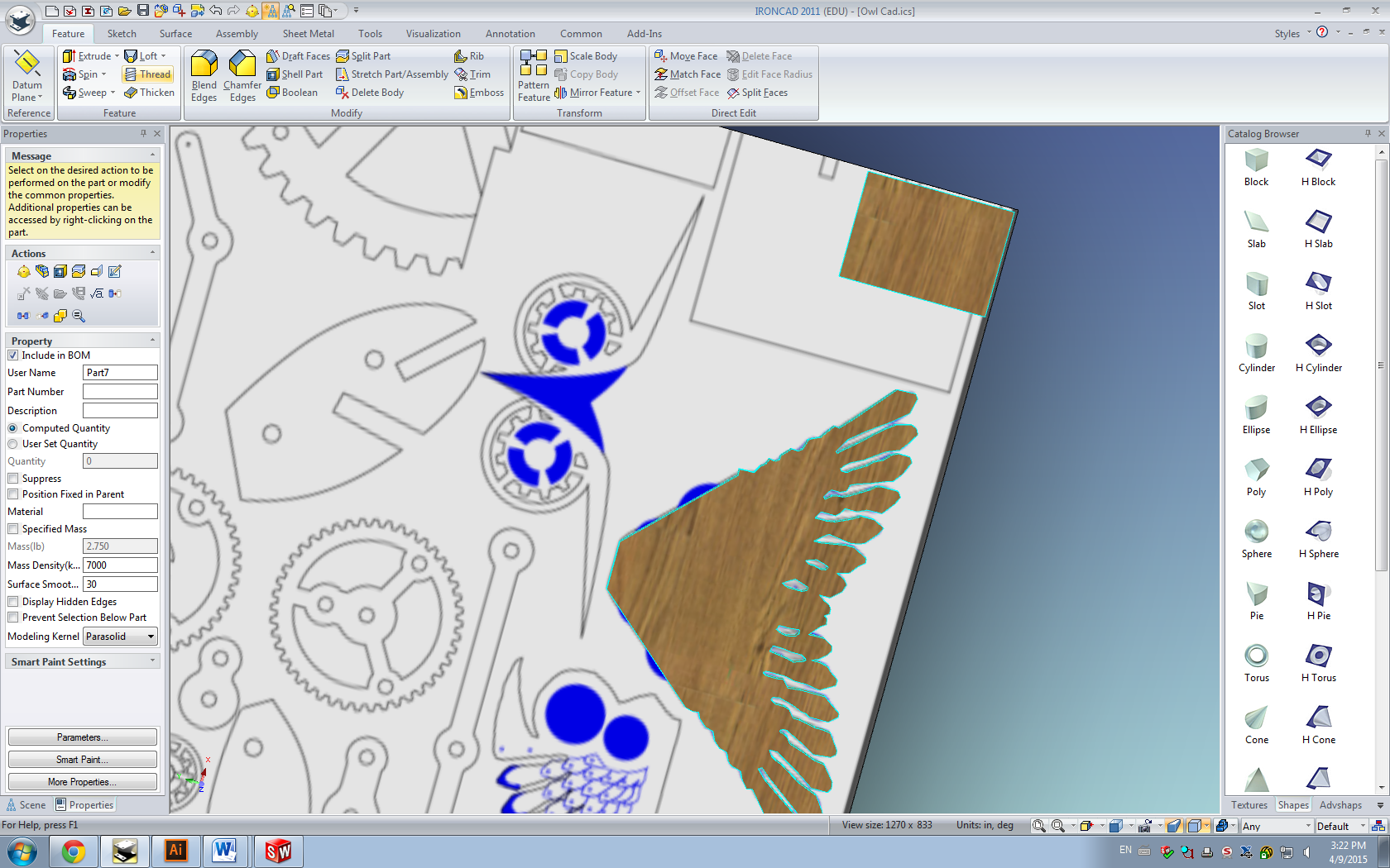
I also opted to have this slab as a separate part from the rest of my design, because I wasn’t entirely sure how parts and textures interacted with one another and I didn’t want to texture my final design with a horribly stretched screenshot of my .ai files. However, this actually proved inconvenient, as IronCAD had issues giving a plane for all of the extruded features to share–it did not enjoy creating extrusions in free space. To solve this, I created a second slab that was part of the same part as the rest of my design, which I placed in the corner. I then instructed IronCAD to make my extrusions in the plane of this smaller slab, which ensured that my extrusions were generated in the same part.

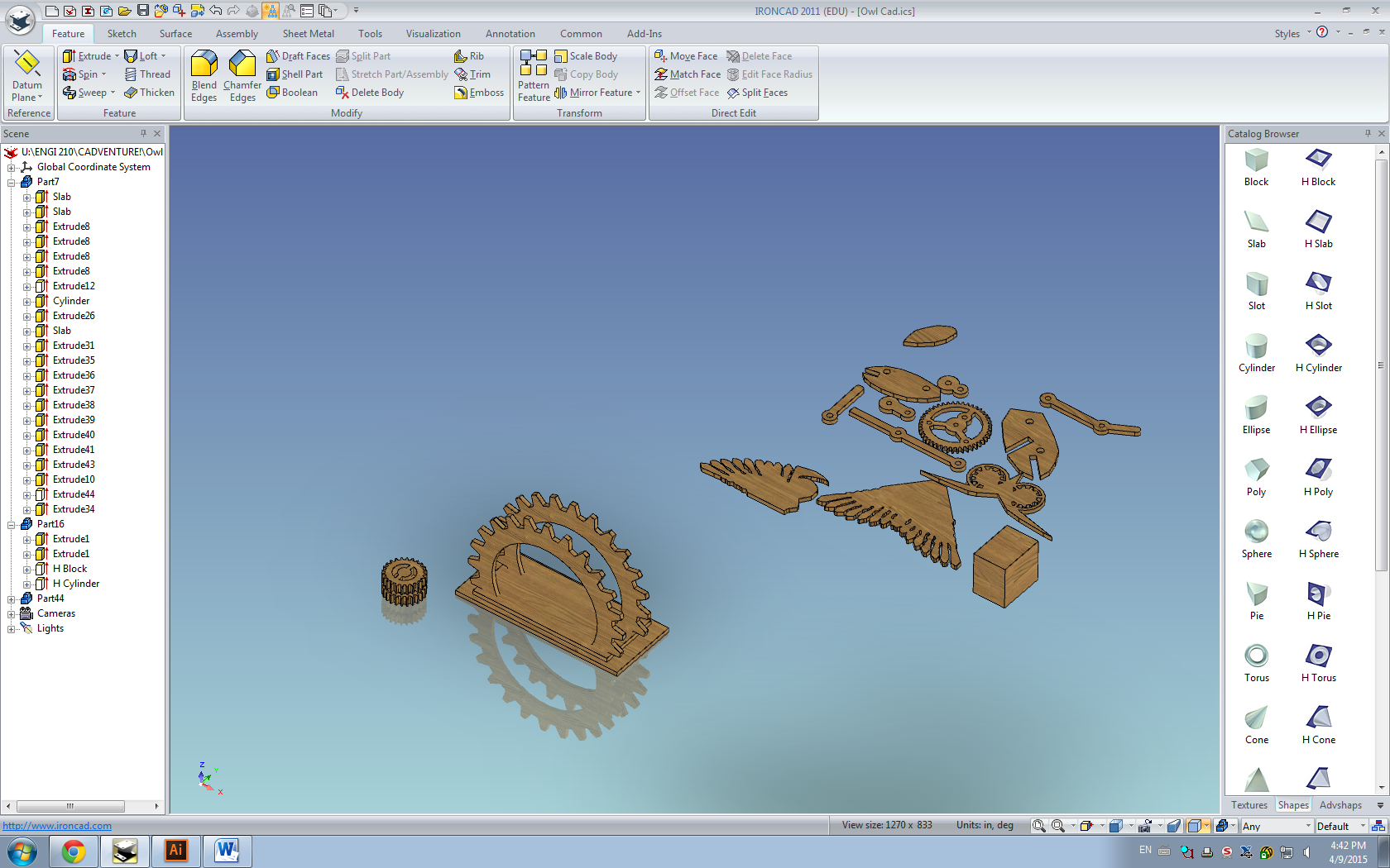
The completed extrusions of the rest of the pieces are shown above. The large gear, which I had actually created earlier, is also shown to indicate that the dimensions are correct. I did end up tracing the internal pattern for this gear (the gear I generated was solid on the inside, while the final gear does have cut-outs). I discovered that the extrude wizard can also “extrude” the removal of material, allowing me to use the same trick as before–tracing the pieces from the projection–and using the anti-extrusion to cut into the already-made gear. I then deleted the projection slab and prepared to clone and assemble the rest of the owl.
Assembly proved fairly straightforward after the finagling with the extrusions. I largely used the triball (which did require some creative positioning at some points, such as orienting the body pieces, which have no planar surfaces for the triball to define its central axis) to translate and position my pieces into the final product.
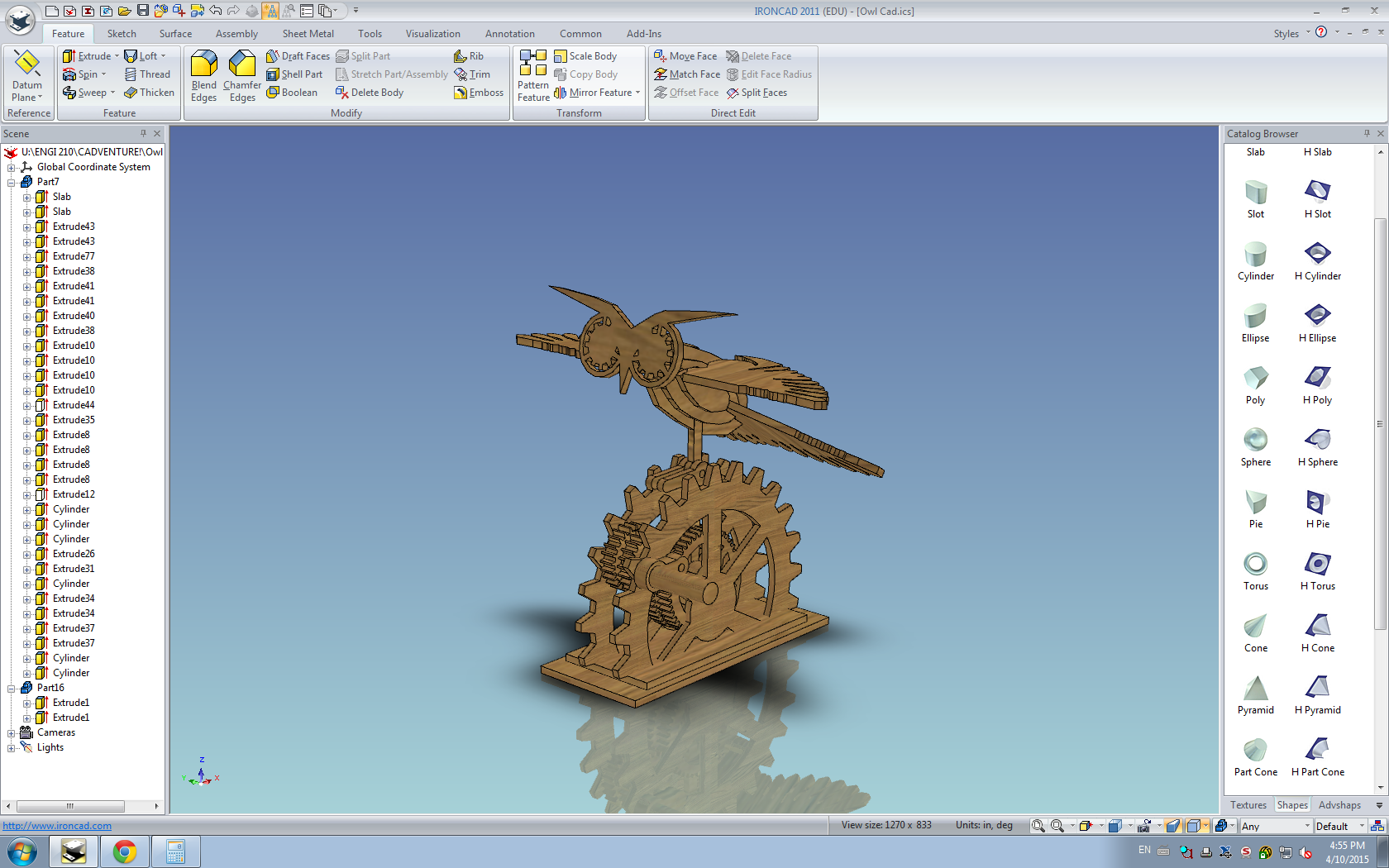
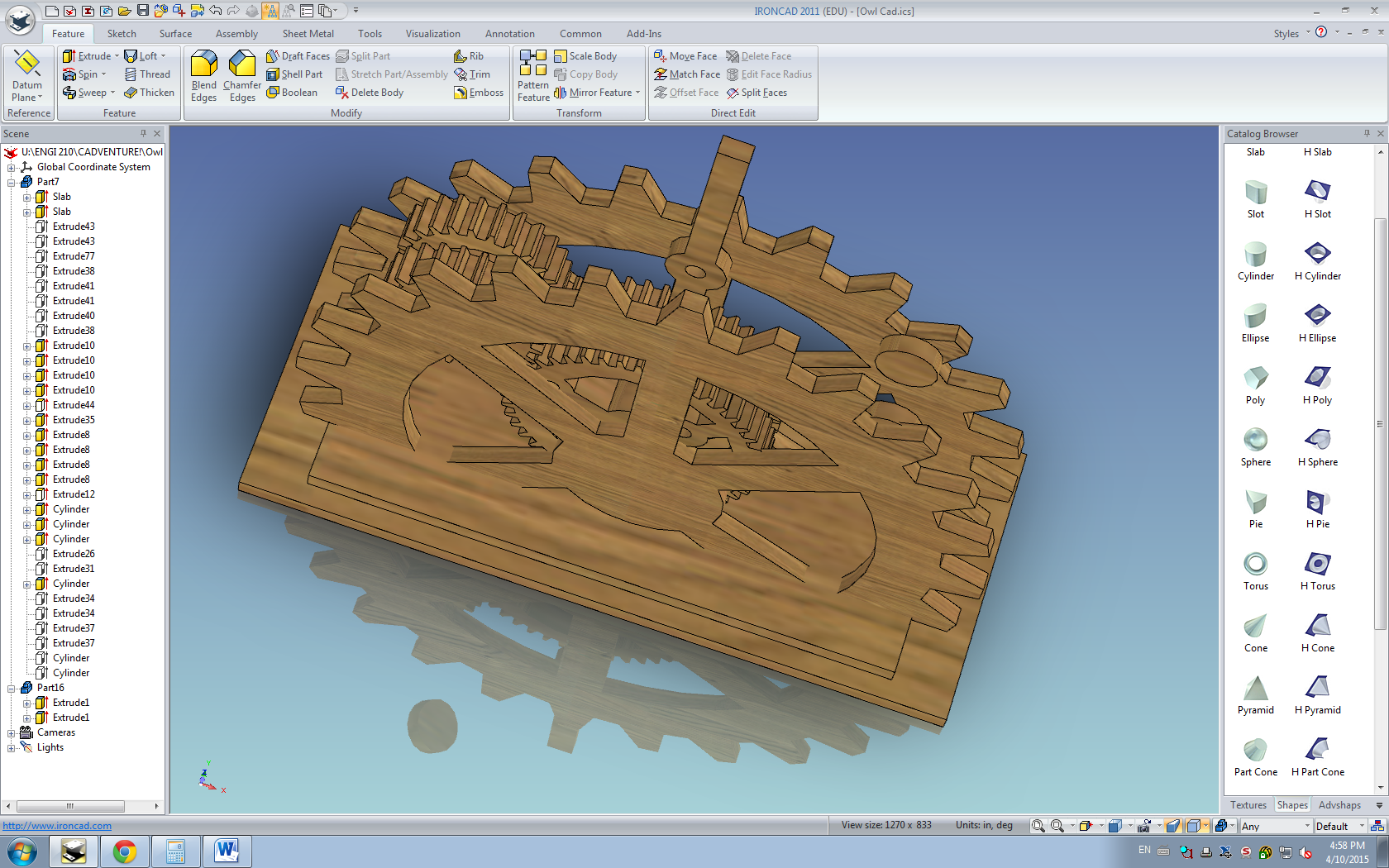
After many hours, many failures, and many, many error messages, I was finally able to generate a CAD version of my midterm project. With a lovely virtual walnut finish, to boot. The rendering took a surprisingly large amount of time to complete.
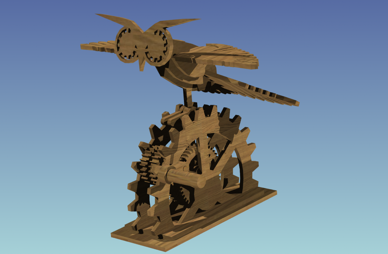
Real owl and fake owl, side by side. Endorsed by late-nights in the OEDK and coffeehouse.

