For our midterm project, we (Art and Ibrahim) built a working roulette table! Overall, this was a really fun experience being able to think of an idea on our own and then see its progression through the three gates. We’re both really proud of our final design and hope y’all can play around with it!
Our Process
To start, we first needed to decide what mechanism we wanted to replicate. We ended up choosing Mechanism #24 as we thought it had a variety of possibilities and was somewhat easy to achieve. For our initial design, our goal was to have two layers of this mechanism.

Figure 1: Mechanism #24 used as the basis of our project
Gate 1
For this first gate, we ultimately wanted to clarify and create a clear outline of what our design would look like, what each moving part would be, and how each moving part would connect. We ultimately decided on a two-layer box that would house the mechanisms with the bottom layer turning the turret in a CCW direction, while the second layer spins the actual roulette table in a CW direction.
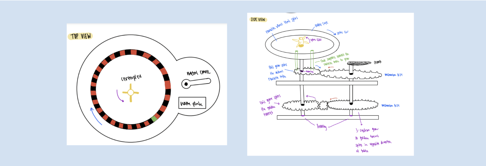
Figure 2: Sketch of Design
Low Fidelity Design
We made our low-fidelity prototype out of cardboard, straws, and styrofoam to get a better understanding of how each part would fit together and to make sure that the gears would spin and rotate the way we wanted them to. For this, the cardboard was used for the gears, the straws were the dowels, and the styrofoam was the main housing and crank. Overall, this design was a success as the table was able to be spun and each moving part could move on its own. For this, we did not double-stack the gears and saw how frequent it was for the gears to slip past each other, so for future models, we decided that implementing double-stacked gears is extremely important. One big piece of feedback that we got from this prototype was that our design is too big, so for future prototypes, we shrunk our overall gears and shapes by 40%.
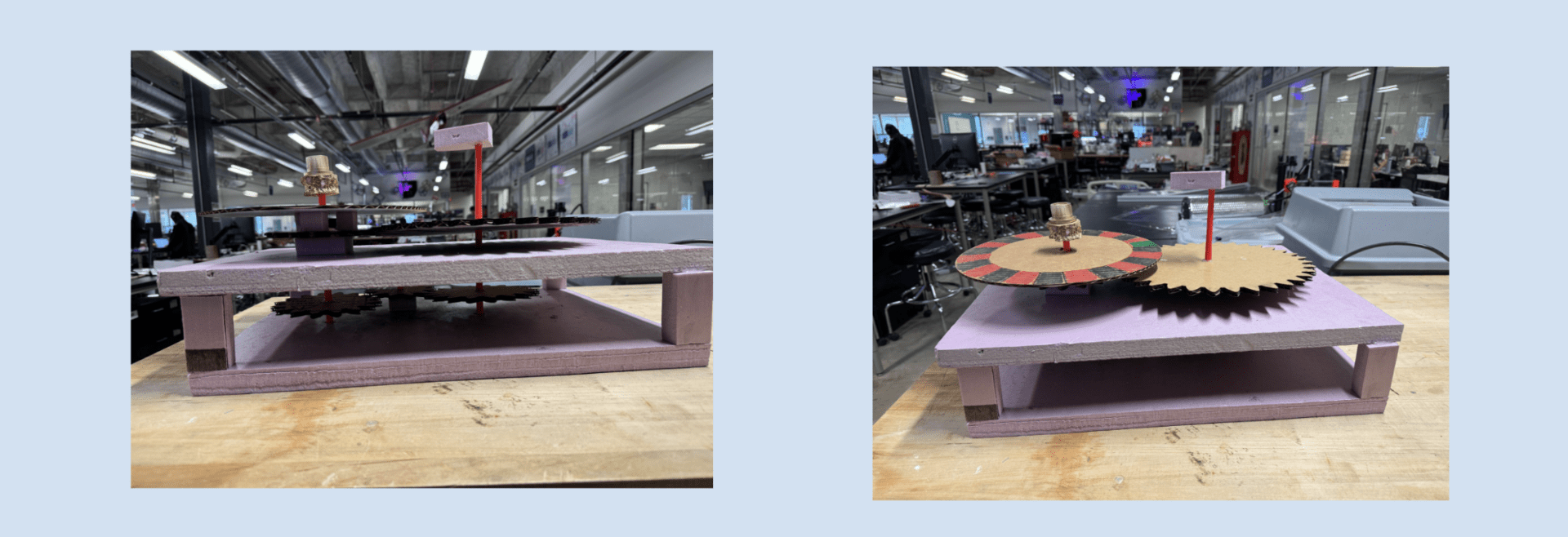
Figure 3: Low Fidelity Prototype
Medium Fidelity
Our medium-fidelity prototype focused more on gear rotation and making sure our gears were moving smoothly and properly. Therefore, we used laser-cut wood for this model and made them the actual size of our final prototype to ensure that dimensions would be accurate, especially since the gears have to be inline vertically. Moreover, a key part of this design was to ensure that the size of the first row of gears would work with the gears in the top row. To keep the gears situated, we used silly putty to attach them to the dowel, but for our final design, we decided that wood glue would work.
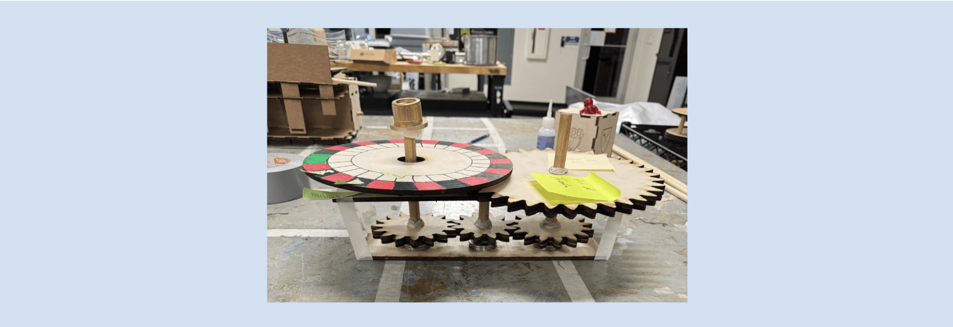
Figure 4: Medium Fidelity Prototype
Vinyl Cutter and Water Jet Cutter
To satisfy our vinyl and metal processing requirements, we used the vinyl cutter to create a stencil that would make it easy to paint the red and black components of our roulette table. This rested on the uppermost platform of our 3-platform roulette table. We used the water jet cutter to make the spinning turret that would sit in the middle of our roulette table. The waterjet cutter was a little confusing to get started at first, but after looking at the instructions and getting some help from the lab assistants, we were able to cut it out almost perfectly. For some reason, the middle hole didn’t cut completely, which may be because of the thickness of the material or the overall path, but we had to use a drill press to help clean off the middle of our turret. In terms of post-processing, we sandblasted the material to clean it up and remove any rust/residue, and then spray-painted it gold to match the actual color of a spinning turret.
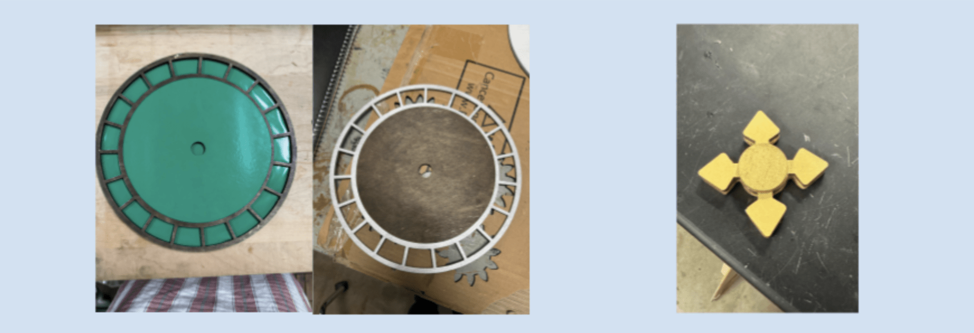
Figure 5: Usage of Vinyl Cutter and Waterjet Cutter
Final Project
After our second prototype, we knew our gear mechanisms worked, so now we could work on aesthetics and the actual housing and crank of our design. For the box that encased all the gears, we made a finger joint box with a custom design on each side. Finding a kerf value was somewhat difficult, but we ended with a value of 0.0085 inches. We found that this value fits our wood material almost perfectly. After cutting these pieces, we sanded them slightly, just to ensure that they would be smooth, and then stained them. To build our spinning table, we constructed it with three layers. The first layer was an all-white circle, the second layer was the cutouts of each number, and then the last layer was the actual slots the ball would be able to fall in.
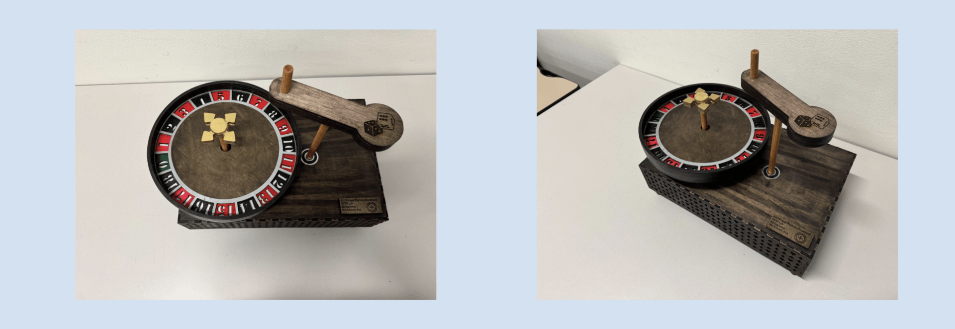
Figure 6: Final Project
Successes and Failures
Overall, we didn’t have too many failures that we weren’t able to address, but some issues that arose were: the metal piece not being cut fully in the middle, our first design being too large, and making sure our gears were spaced correctly and ideally so the table could spin correctly. This was a really fun project that both of us really enjoyed. Although we spent a lot of time working on this, seeing the final design at the very end work perfectly is super rewarding! Throughout the entire making process, it was essential to maintain clean workspaces, especially the laser cutter, since it was frequently used.
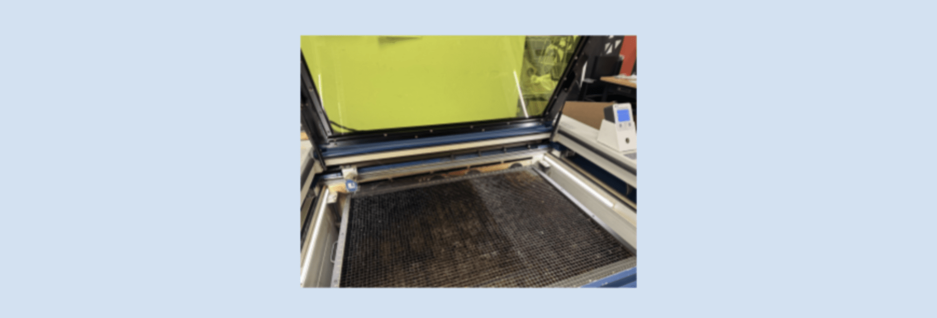
Figure 7: Clean Workspace (Laser Cutter)
Link to Presentation
Link to Video of Final Project
Finally, we have included a cost breakdown of the project below:
| Item | Quantity | Estimated Cost ($) | Source |
| Laser Cuttable Birch Wood | 8 Sheets @ $12/Sheet | 96.00 | home depot |
| 0.25” Steel Sheet | 1/10 Sheet | 2.60 | amazon |
| Vinyl Roll | 1/10 Roll | 0.70 | amazon |
| Spray Paint | 1 Can | 13.97 | amazon |
| Wood Stain | 1/4 Tin | 2.11 | amazon |
| ¼” Dowels | 2 hr | 5.99 | amazon |
| 35mm diameter Bearings | 5 pcs | 7.50 | amazon |
| Design Engineer | 40 hr @ $29/hr | 1,160.00 | ZipRecruiter |
| Laser Cutter Usage | 8 hr @ $0.82/hr | 6.56 | epiloglaser |
| Water Jet Cutter Usage | 12 hr @ $19.68/hr | 19.86 | wardjet |
| Total Costs: | 1,315.29 |
