Hello again! I am back this week with the next homework assignment: creating one of the 507 Mechanical Movements in Adobe Illustrator! As a precursor, I would like to note that before this assignment I have used Illustrator quite a bit, and am probably around a proficient to advanced level in using it. This means that some of the concepts and tools I used were easier for me to choose since I already have used them so much.
Anyways, let’s get into the project. The first thing I needed to do was to select the mechanical movement I wanted to model. Looking through the different ones available, I was drawn to movement no. 156 because I liked how it converted a rotational motion to a rectilinear motion. This movement can be seen in Figure 1 below.
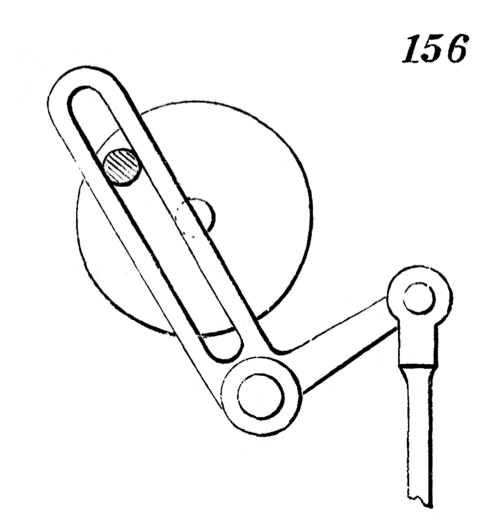
Figure 1: The Original Mechanical Movement
Getting into Illustrator, I began by making the basic shapes, like circles and rounded rectangles. On of the more complex components of this movement is the L-shaped slot that oscillates back and forth. For this specific piece, I began by creating an upright rounded rectangle to make up the slot component, and a sideways regular rectangle to make up the base component. I proceeded to use the scissors tool to cut each shape where the two shapes intersected, making it so that there were no overlapping areas between the two. Once the shapes had been cut I joined them to create one continuous shape. Once the shape had been formed, I used the Direct Selection Tool to narrow the bottom rectangular section and to round the corner joining the original two shapes. This process can be seen below in Figure 2.
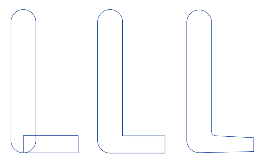
Figure 2: The Snipping Process
I continued using these techniques to build up the pieces until I had a finished product. This final result can be seen in figure 3. Along with that, the actual illustrator file can be found here!
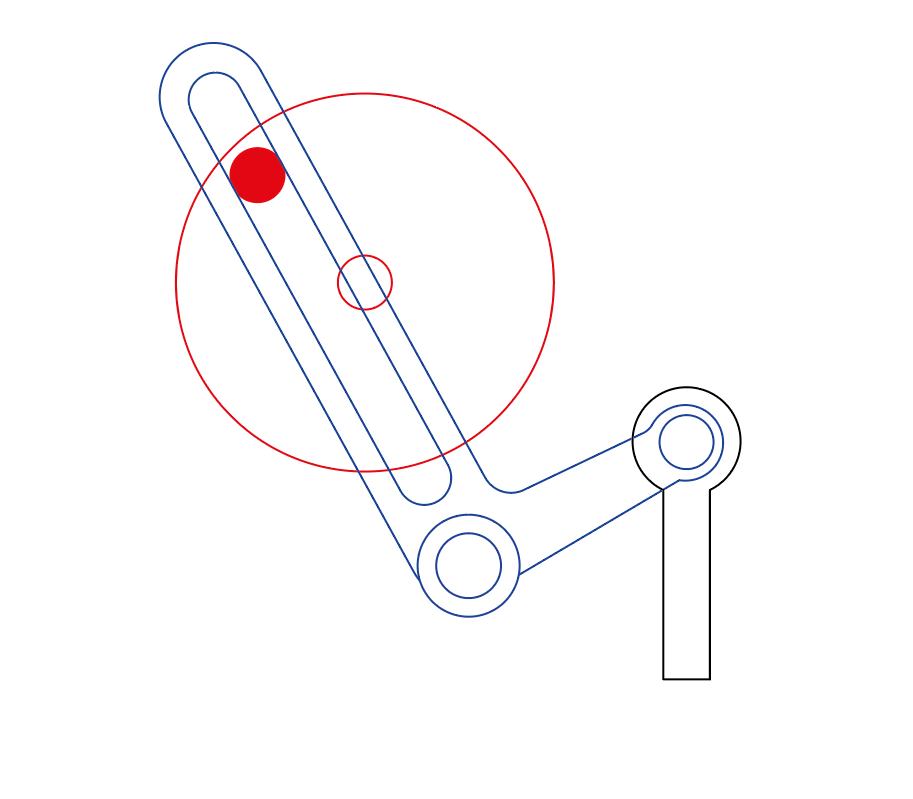
Figure 3: The Final Mechanical Movement!
One of the difficulties I faced through most of this assignment and am still not entirely sure how to mitigate is trying to work out the spacing and positioning of the pieces once “new” pieces have been formed using the scissors tool. For plain shapes, there are clear center-points on each of the sides, and the center mark is very clearly in the center of the shape. For the new shapes, my experience was that some of the center-points just disappeared and I could no longer use the center marks to align other pieces within a section of the object. For example, I placed the slot in the L piece after the L had been formed. But there was no clear way to tell if the slot was exactly midway between the upper L side. So, for cases like these I simply placed it where it looked to be the most central, but it is definitely not exact.
Despite these difficulties, I am very satisfied with the final result! I look forward to cutting this out on the laser cutter and adjusting any parts to fit the tolerances.
Finally, I’ll do a quick cost assessment of creating this file. I worked for 1.5 hours, and at $20/hr this amounts to $30 total. There were no material costs, so this $30 is the complete cost.
